





Description
Technical Specifications Matrix
| Parameter | Specification Detail |
|---|---|
| System Architecture | Standard 6U Single-Slot VMEbus Specification Rev. C.1 / VME64 |
| Processor Assembly | Intel Celeron Socket 370 with MMX architecture |
| System Memory Capacities | 32 MB to 512 MB PC133 SDRAM (Dual-ported to VMEbus) |
| Onboard Flash Mass Storage | 16 MB to 64 MB bootable Solid-State Flash disk array |
| Bus Bridge Controller | Tundra Universe II™ (VME-to-PCI interface) |
| Video Processing Controller | 64-bit Intel AGP SVGA with 2 MB or 4 MB internal SGRAM |
| Network Interfaces | Dual channels supporting 10Base-T and 100Base-TX (RJ-45) |
| Peripheral I/O Array | 2 × 16550-compatible serial ports, PS/2 mouse/keyboard ports on front bezel |
| Counter/Timer Arrays | 3 × 82C54-compatible 16-bit software-programmable timers |
| Data Integrity Systems | Integrated programmable Watchdog Timer, battery-backed non-volatile SRAM |
| OS Compatibility Platform | MS-DOS, Windows NT/2000/XP, VxWorks, QNX, Linux |
| Operating Temperature | 0 to +65°C (32 to 149°F) standard continuous industrial envelope |
Product Introduction
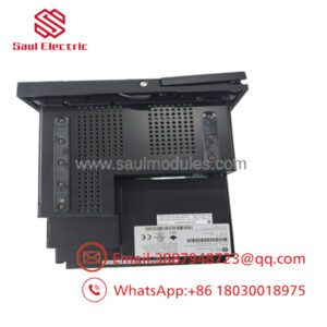
The GE VMIVME7698 (often labeled VMIVME-7698) is a highly deterministic, single-slot 6U VMEbus Single-Board Computer (SBC) engineered by VMIC (a GE Fanuc company) for high-availability systems, including the Speedtronic Mark VI turbine control platform. Functioning as an IBM PC/AT-compatible computer adapted into a heavy industrial Eurocard format, the card is frequently deployed to handle complex master workstation operations, multi-node plant networks, and diagnostic calculations.
Equipped with an Intel Celeron Socket 370 processor, the VMIVME7698 bridges typical PC architectures with deterministic backplane automation using an onboard Tundra Universe II PCI-to-VMEbus bridge chip. Its onboard SDRAM is uniquely dual-ported to the VMEbus, meaning that neighboring processing nodes or I/O cards can access the controller’s main memory parameters simultaneously without creating processor lag. Combined with a bootable non-volatile flash disk, battery-backed SRAM, and a hardware watchdog timer, the module ensures robust execution for real-time operating systems like QNX, VxWorks, and Windows NT.
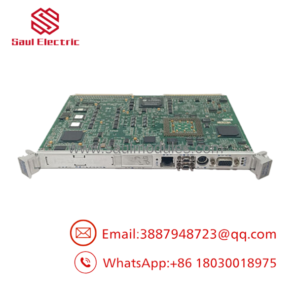
- VMIVME7698
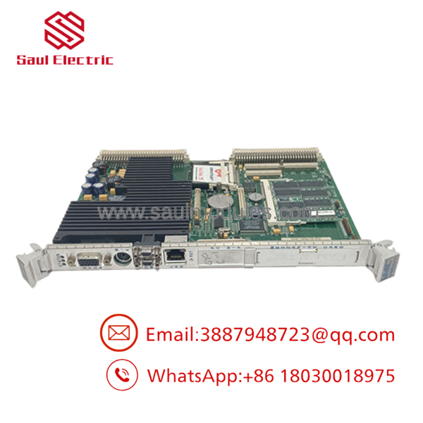
- VMIVME7698
Installation & Configuration Guide
Stage 1: Pre-Installation Preparation (Estimated Time: 20 minutes)
- ⚠️ Safety First: The VMIVME7698 single-board computer orchestrates major systemic network traffic and real-time database paths. Never remove or insert this processor module while the host VME backplane chassis is energized. Disengage the master power distribution breaker supplying the card cage, lock out and tag out (LOTO) all power feeds, and ensure no field loops remain active.
- Tools Required: Grounded anti-static wrist strap, flathead screwdriver, specialized IC extraction tools (if replacing flash storage modules), laptop with your target platform software configuration.
- Data Backup: Ensure you have fully cloned your system BIOS preferences and local flash drive files (including runtime system setups, network configuration scripts, and IP definitions) onto external validation media before extracting the board.
Stage 2: Replicating Board Jumpers & Address Maps (Estimated Time: 10 minutes)
- Place the replacement VMIVME7698 module on a clean, static-shielded workbench.
- Position the retired card side by side with the replacement board.
- Locate the physical hardware jumper arrays on the main board layout. These blocks govern critical boot paths, VME slave address regions (Short I/O or Standard mapping), interrupt request configurations (IRQ1 to IRQ7), and Endian hardware byte-swapping profiles.
- Using needle-nose pliers, carefully match and replicate every jumper block setting from the old board onto the new assembly.
Stage 3: Card Insertion & Mechanical Fastening (Estimated Time: 10 minutes)
- Check the high-density rear P1 and P2 connector prongs on the replacement board to ensure no pins are bent or oxidised.
- Swing out both the upper and lower injector/ejector handles on the card faceplate.
- Slide the board edges carefully into the dedicated guide tracks of the targeted single-slot location.
- Push the card straight back until the handles touch the rack frame lips.
- Snap both ejector handles inward simultaneously to inject the multi-pin array into the backplane seat. Lock the upper and lower faceplate screws down tightly.
- Reconnect your front panel peripherals (PS/2 links, SVGA monitor lines, and dual RJ-45 network connections).
Stage 4: Power-On & BIOS Setup (Estimated Time: 20 minutes)
- Re-energize the main VME control rack power supply.
- Hook up an industrial monitor to the front J3 video port. Watch the initial power-on self-test (POST) sequence screen.
- ⚠️ Troubleshooting: If the unit generates an error or a continuous beep loop during boot, press the
DelorF2key to enter the system BIOS setup screen. Verify that your boot device priority is pointed to the primary onboard solid-state flash card rather than an unpopulated external drive. - Allow your core industrial operating system (such as QNX or Windows NT) to initialize completely. Run a local diagnostic bus test to verify that the Tundra Universe II bridge is communicating with adjacent VME I/O slaving devices.
Frequently Asked Questions (FAQ)
Can I hot-swap the controller board while the system is operating?
Absolutely not. The functions as a central system master processor on the shared VME data highway. It does not possess live insertion or hot-plug structural protection lines. Extracting the card under power will result in backplane voltage transients that can permanently fry the on-board chipset components and immediately lock up or disrupt all other cards on the VME rack.
How is the related to the GE Mark VI part number IS215UCVEM09A?
Within the GE Speedtronic Mark VI turbine control system, General Electric packaged the physical single-board computer into customized product configurations known as the IS215UCVEM series (specifically variations like UCVEM09A). The underlying processing component and motherboard layout on the carrier are the exact same VMIC-designed hardware.
Why is the dual-ported RAM design important for multi-processor configurations?
Standard computer architectures require the main processor to actively manage all inbound and outbound bus data requests, creating memory bottlenecks during high-speed actions. The uses memory that is dual-ported directly to the VMEbus. This means that external VME co-processors or I/O boards can write to or read from designated memory buffers simultaneously without interrupting or stalling the active clock cycles of the main Celeron CPU.
What should I check if the Tundra Universe II VME-to-PCI bridge fails to resolve?
If your system boots but cannot pass data to other VMEbus slaved units, first ensure that your hardware jumpers governing VME endian conversion and address decoding are aligned with your system documentation. Next, check your operating system hardware logs to confirm that the Universe II device driver is loading correctly during early boot initialization phases.
Why are these specialized single-board computer modules sold as “New Surplus”?
Since technology for industrial single-board processors has advanced through subsequent platform updates, these legacy Celeron Socket 370 assemblies are no longer in mass active assembly lines by the original manufacturer. Our warehouse inventory comprises New Original / New Surplus units—unused factory spares preserved in pristine storage from plant liquidations, overstocks, or project cancelations. This provides direct access to identical hardware replacements with no long manufacturing lead times.


 Start Chat


