





Description
Key Technical Specifications
| Parameter | Specification Value |
|---|---|
| Module Classification | Multi-Function Field Input/Output Remote Node |
| ADC Resolution | High-precision 16-bit internal conversion architecture |
| Input Channels | 8 Multi-signal configurable Analog/Digital channels |
| Analog Input Signal Profiles | 4–20 mA current loops, 0–10 VDC, Thermocouple, RTD inputs |
| Input Impedance | > 100 kΩ (Voltage Mode) / 250 Ω (Current Mode) |
| Sampling Processing Speed | Up to 1 kHz internal burst tracking speed |
| Control Power Supply Bounds | 24 VDC nominal base operating feed (±15% tolerance window) |
| Bus Internal Power Load | Approx. 480 mA draw via rack backplane |
| Network Interfaces | Dual redundant RS485 interfaces, local CAN, optional Ethernet |
| Industrial Protocols | IEC 61850, DNP 3.0 Level 2, Modbus RTU / Modbus TCP |
| Enclosure Rating & Mount | Standard IP20 chassis housing / Direct DIN-rail or panel layout |
| Operating Thermal Matrix | −40 to +75°C (Extended industrial wide-temperature profile) |
| Mean Time Between Failures | MTBF > 100,000 operational hours |
Product Introduction
The GE WESDAC WEA13-13 2508-21001 functions as a high-reliability, intelligent distributed control and substation data acquisition module engineered to operate in harsh electrical utility environments. Deployed inside distribution network substations, remote terminal units (RTUs), and power management lineups, it consolidates analog processing and digital monitoring into a single space-saving footprint. It handles the interface load for heavy-duty switchgear cells, wind farm collection hubs, and water infrastructure treatment plants.
The unique capabilities of the WEA13-13 layout stem from its multi-signal flexibility. Rather than specifying individual, single-purpose tracking cards for different instrumentation loops, engineers configure the 2508-21001 to simultaneously handle standard 4–20 mA telemetry loops, 0–10 V voltage nodes, and direct RTD temperature sensor links. This dynamic capability lowers hardware spare costs across the facility while its high-grade digital filtering blocks eliminate the high electromagnetic noise levels generated by transformers and variable frequency drives (VFDs).
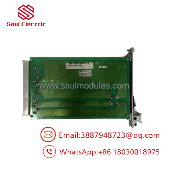
- WEA13-13 2508-21001
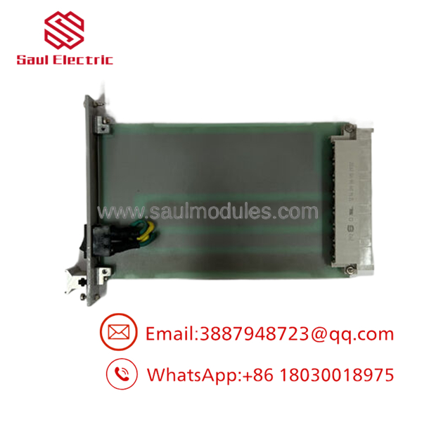
- WEA13-13 2508-21001
Installation & Configuration Guide
Stage 1: Pre-Installation Preparation (Estimated Time: 15 minutes)
- ⚠️ Safety First: Disconnect or open the primary 24 VDC external power feed switches driving the target I/O bay. Confirm the local area environment is safe and clear of live potentials using a digital multimeter. Lockout and tagout the feeder breakers before modifying internal electrical connections.
- Tools Required: Grounded static-control wrist strap, small terminal screwdriver, wire labeling markers, Fluke 115 multimeter, and a terminal laptop with GE configuration utility tools.
- Data Backup: Link your service laptop to the communications port. Pull down the active register mapping parameters and device node addressing file before sliding the damaged component loose.
Stage 2: Removing the Old Module (Estimated Time: 5 minutes)
- Ensure your anti-static ESD wrist band is firmly strapped to an unpainted zone on the enclosure frame.
- Carefully unplug the terminal block wiring connectors from the faceplate header pins. Do not put tension on the internal copper cores; pull via the molded connector clip housings.
- Release the upper and lower mechanical DIN-rail locking clips using a small flat-tip tool.
- Unseat the module from its bracket path and move it to a safe static-shielded work table.
Stage 3: Installing the New Module (Estimated Time: 10 minutes)
- Extract the new surplus WEA13-13 card from its static-barrier package while maintaining full ESD protection protocol.
- Position the rear mounting guides over the DIN-rail edge and rotate downward until you hear the structural latch clips lock into place with an audible click.
- Configuration Transfer: Power up the local 24 VDC feed and connect your field interface tool. Write the identical node map configuration parameters and communication baud flags onto the replacement 2508-21001 module. Ensure the sensor signal select maps (e.g., matching a 4–20 mA scale on Channel 1) perfectly align with physical instrumentation prints.
- Re-seat the terminal strip wiring blocks back onto the header assemblies, tightening the retaining hardware to avoid signal contact drops.
❗ Configuration Check: [ ] Hardware DIN-rail mounting tabs are fully snapped into position. [ ] System communications address variables mirror the master SCADA register map. [ ] Wiring headers are fully engaged and locked.
Stage 4: Power-On & Testing (Estimated Time: 10 minutes)
- Fully re-engage primary instrumentation lines and field sensors.
- Watch the front diagnostic LED cluster initialize. The module should complete its power-on self-test (POST) sequence and transition into a solid green status state with zero error indicators.
- Query the device registers from your engineering SCADA node to verify that 16-bit analog-to-digital data inputs read clean process values without signal noise spikes.
- Verify data transceiver polling behavior by checking the flickering patterns on the dual RS485 communication line indicators.
Strategic Quality Control & Inspection Process
To guarantee zero-downtime integration for aging infrastructure grids, every surplus and legacy WESDAC WEA13-13 component is processed through an exhaustive laboratory verification pipeline.
- Inbound Traceability & Board Inspection: Part code configurations are verified against original manufacturing drawings. Card layouts are examined under magnification to confirm there are no trace micro-cracks, capacitor age fatigue, or corrosion on terminal pin tracking grids.
- Multi-Signal Phase Injection Accuracy Sweep: The module is benched on a precision signal testing layout. We pass automated step inputs across voltage, current, and RTD temperature modes to ensure the internal 16-bit ADC tracks metrics cleanly within original factory accuracy limits.
- Substation Comm Protocol Validation Loop: The card is linked to an active SCADA network simulator ring. Communication performance is checked across full DNP3 and Modbus registers under continuous transmission loads to confirm zero transmission drops or packet frame retries occur.
- Thermal Run-In Stress Validation: The 2508-21001 is operated continuously for 24 hours under thermal testing parameters to isolate and eliminate premature field module failure issues before dispatch.
- ESD Sealed Containment Packaging: Following testing clearance, clean dust caps are fitted to exposed ports. The complete card is packed inside specialized static-barrier wrapping, surrounded by thick protective foam inserts, and shipped in a double-wall corrugated carton along with its signed laboratory quality pass slip.
Frequently Asked Questions
Does the 2508-21001 support online hot-swapping during operations?
Yes. The physical chassis configuration and pin-mating geometry of the module are designed to handle hot-plug operations safely. This allows a technician to replace a damaged card without killing control power to adjacent I/O nodes inside the rack assembly. However, note that pulling the module will instantly break data transmission from any field instrumentation connected to its terminal block, so upstream control loops must be set to manual mode prior to extraction.
Can I run this module using a standard 120/240 VAC power source?
No. The 2508-21001 requires a steady, low-voltage industrial 24 VDC power supply (operating within a standard ±15% range). Connecting raw mains AC power directly to the terminal lines will instantly ruin the internal board traces, microprocessors, and interface isolation chips. If you have an AC-powered panel lineup, you must install an intermediate industrial power supply module (such as the GE WES5120 series) to step down the potential to 24 VDC before feeding this card.
How do I modify an individual channel to read an RTD instead of a 4–20 mA loop?
The hardware configuration of the 2508-21001 features fully software-programmable input selection paths. There is no need to crack open the plastic housing to alter physical jumpers on the board. Simply connect your engineering terminal laptop via the setup software utility, navigate to the channel configuration register matrix, toggle the target channel input type, and load the new profile parameters down to the module’s non-volatile memory.
What happens to field values if the master SCADA communications link drops out?
The features built-in data caching and local diagnostic routines. If the primary upstream serial or Ethernet connection drops out, the module buffers critical process alarms locally. Once the network layer is restored to an active polling state, the card automatically re-transmits the cached log blocks to ensure complete data integrity across your plant history logs.
Why source a new surplus module instead of upgrading the entire I/O bay?
Migrating a legacy substation facility or process automation network to a current-generation platform introduces high structural engineering costs. It requires completely rewriting master controller logic maps, modifying physical panel layouts, re-drafting electrical prints, and repeating time-consuming validation protocols. Sourcing a genuine surplus 2508-21001 module allows you to drop the exact architectural fit back into your layout in under 30 minutes, preserving your current code and engineering investments. Every module includes our 1-year independent depot replacement warranty.




 Start Chat


