





Description
Core Product Summary
The Honeywell DCP71150C012010H0 is the complete order code for the Honeywell DCP-711, a model within the Honeywell DCP 700 series of microprocessor-based Digital Control Programmers. The DCP 700 family generates setpoint-versus-time profiles from ramp and soak segments and executes closed-loop PID temperature or process control against them, with DCP711-denominated units built on the series’ standard dual-channel-capable hardware and operator interface.
The instrument stores up to 39 programs with up to 99 segments each and supports up to 12 event outputs that can be time-, process-variable-, or deviation-based. Up to nine PID parameter sets can be defined and assigned per segment, and programs can be cycled up to 9,999 times. Inputs cover thermocouples, three-wire RTDs, and DC current or voltage signals; control outputs include a 4–20 mA current-proportioning output (600 Ω maximum load) and time-proportional switching through external relays. The unit is powered from 120 Vac, 50/60 Hz, with a consumption of 40 VA, and is designed for panel mounting with a rear screw-type terminal block.
Key Technical Specifications
| Parameter | Value |
|---|---|
| Product type | Digital Control Programmer (setpoint profiler with PID control) |
| Series / model | Honeywell DCP 700 series, DCP-711 model; order code DCP71150C012010H0 |
| Control principle | Microprocessor-based ramp/soak setpoint programming with PID control |
| Channels | Two-channel capable (Channel 1 / Channel 2, with duplex heat/cool operation) |
| Programs / segments | 39 programs; up to 99 segments per program |
| Program cycle count | 0 to 9,999 cycles |
| Segment types | Soak, guaranteed soak (band 1–100 PV units), time ramp (1–999.9 or 1–9999 PV units/time unit), position ramp, external-contact stepped ramp |
| Segment duration range | 0.00 to 255.59 (hours/minutes or minutes/seconds, configurable per program) |
| Event outputs | Up to 12 events; time-, PV-, or deviation-based; on/off time 0.00–255.59 |
| PID sets | Up to 9 PID combinations, selectable per segment |
| PV scaling | PV ratio 0.000–9.999; configurable PV bias |
| Inputs | Thermocouple, three-wire RTD, DC current, DC voltage (twisted, shielded leads; shields to terminal 13) |
| Current output | 4–20 mA current-proportioning control or programmer output; 600 Ω maximum load |
| Auxiliary output | 4–20 mA linear output, configurable as setpoint, PV, or output retransmission; 600 Ω max load |
| Time-proportional output | External relay per channel, 24 Vdc / 75 mA; user-supplied 24 Vdc ±5%, 1 A external power supply required; total event/alarm/time-proportional relays limited to 15 |
| Alarm outputs | CPU failure, PV over/under range limit, error condition, Channel 1 and Channel 2 run/hold (24 Vdc, 75 mA each) |
| Remote operation contacts | Run, hold, reset, PV start / segment advance, sync, channel select, external program start (2 inputs) |
| External program selection | Closed-contact binary selection for all 39 programs |
| Communications | DMCS network option for host-computer connection |
| Memory module | Program upload/download to memory module supported |
| Operator interface | Membrane keyboard with audible feedback; 16-segment alphanumeric display plus three 7-segment displays (SP, TM, PV); 16 status LEDs |
| Power supply | 120 Vac ±12 Vac, 50/60 Hz ±1 Hz; consumption 40 VA |
| Ambient operating limits | 0 to 50 °C (32 to 122 °F); relative humidity 10–90%; vibration 0–0.02 G; mounting angle ±10° |
| Noise rejection | Common mode 120 dB down at 250 Vac; normal mode 60 dB down at 2× span |
| Weight | Approximately 13 lb (6 kg) |
| Installation | Panel mounting with supplied mounting brackets; rear screw terminal block |
Detailed Product Overview
The DCP71150C012010H0 is built for processes that must follow a defined thermal or process-variable profile rather than hold a single setpoint. Heat-treatment furnaces, ovens, and similar batch thermal equipment are the classic use case for this class of instrument: the operator enters a program as a sequence of ramp and soak segments, and the DCP 700 drives the control output so that the process variable tracks the programmed setpoint curve, while PID control handles the dynamic response of the process itself.
The programming model is what distinguishes this unit from a simple temperature controller. Each segment can be a soak (hold a setpoint for a duration), a ramp at a fixed rate, or a ramp driven by an external contact. The guaranteed-soak function is particularly relevant to heat treatment: the soak timer does not start until the process variable enters a configurable band around the setpoint, which prevents the instrument from “counting time” while the workload is still lagging behind the indicated temperature. Segment durations run up to 255.59 in the configured time unit, and the time base can be accelerated for test and commissioning runs.
Event capability is a core integration feature. Up to twelve events can fire on time, on process-variable thresholds, or on deviation from setpoint, letting one profile coordinate auxiliary equipment — circulation fans, quench valves, recorders, annunciators — without an external sequencer. Programs can also branch: on a remote contact the DCP can jump to a chosen segment in the same or a different program, which supports recipes that must react to operator or process conditions mid-run.
Because the instrument supports two channels (with duplex heat/cool splitting possible on Channel 1), it can run two independent profiles, or one synchronized dual-loop profile, from a single panel cutout. Nine PID sets allow different tuning for heat-up, soak, and cooling phases, with segment-level assignment so that the tuning follows the profile automatically.
Selection and maintenance depend heavily on the hardware configuration embedded in the order-code suffix, since the DCP 700 was built to order with input types, output types, and options selected per model number. For replacement purposes, confirming the full code — not just “DCP711” — is essential, because the suffix determines input calibration, output hardware, and installed options.
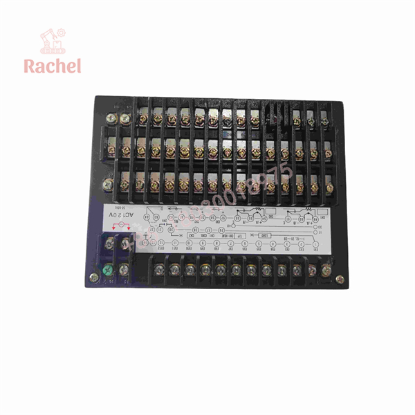
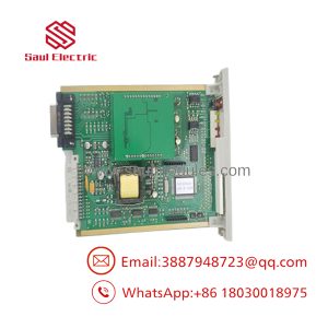
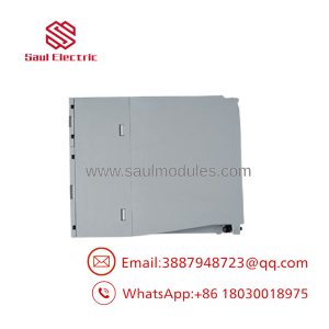
DCP71150C012010H0
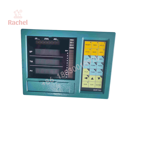
DCP71150C012010H0
System Compatibility & Integration Requirements
| Item / Dependency | Requirement | Practical Note |
|---|---|---|
| Power | 120 Vac ±12 Vac, 50/60 Hz ±1 Hz, terminals 15/16; terminal 14 to earth ground via minimum 14 AWG copper | Power switch/fuse rating 240 Vac, 3 A; consumption 40 VA |
| Sensor input | Thermocouple, 3-wire RTD, or DC current/voltage per installed configuration | Twisted, shielded cable; shield to terminal 13, not grounded at the far end |
| Analog control output | 4–20 mA into maximum 600 Ω | Suits SCR power controllers and valve/actuator positioners |
| Time-proportional switching | External relay per output, 24 Vdc / 75 mA; external 24 Vdc ±5%, 1 A supply | Total of event + alarm + time-proportional relays must not exceed 15 |
| Auxiliary (recorder) output | 4–20 mA, 600 Ω max; configurable as SP, PV, or output | Use for chart recorder retransmission |
| Remote operation | Momentary dry contacts for run, hold, reset, PV start/segment advance, sync, channel select | Contacts connect to terminal 17 common |
| Program selection | Closed-contact binary coding across terminals 43–48 | Selects any of the 39 programs remotely |
| Host communication | DMCS network option (if installed) | Supports supervisory connection and LED indication of host communication |
| Program backup | Memory module | Upload/download of programs from the front panel |
| PID tuning | Up to 9 PID sets, assignable per segment | Default: CH1 uses PID 1; duplex heat/cool uses PID 1 and 2; CH2 uses PID 5 |
Dimensions, Mounting & Connection Notes
- Panel-mounted instrument secured with the supplied mounting brackets; the unit slides terminal-end first into the panel cutout and is clamped with bracket screws and knurled nuts.
- Weight is approximately 13 lb (6 kg); mounting orientation tolerance is ±10° from the intended angle.
- All field wiring lands on a rear terminal block; power on terminals 15 (hot) and 16 (neutral), earth ground on terminal 14 with minimum 14 AWG copper wire.
- Input signal shields connect to terminal 13 only and must not be grounded at the other end; RTD inputs use three copper wires of equal resistance, twisted and shielded.
- Signal, power, event, and ground conductors must be routed in separate bundles per the installation instructions; inductive event/alarm loads require an RC snubber or metal-oxide varistor across the load, and DC relay coils require a flyback diode.
- Ambient limits for installation and operation: 0 to 50 °C (32 to 122 °F), 10–90% relative humidity, vibration 0–0.02 G.
Engineering Selection Highlights
- Program capacity of 39 programs / 99 segments — sufficient for plants running many recipes on one furnace or oven; programs can be copied, cycled, and edited in place from the front panel.
- Two channels with duplex heat/cool support — one unit can control heat and cool outputs on one loop or two separate loops, halving panel space for dual-loop applications.
- 4–20 mA current-proportioning output (600 Ω max load) — drives SCR power controllers and similar analog actuator inputs directly; verify the load impedance of the connected power control stays below 600 Ω.
- Time-proportional output requires external hardware — the switching output drives user-supplied relays at 24 Vdc / 75 mA from a user-supplied 24 Vdc, 1 A supply, with a hard limit of 15 relays across all event, alarm, and time-proportional functions; budget these outputs when planning the panel.
- Guaranteed soak band (1–100 PV units) — ensures soak timing only starts when the workload reaches temperature band; set the band from the actual process tolerance, not the display resolution.
- 120 Vac ±12 Vac, 50/60 Hz, 40 VA supply — check panel transformer capacity and tolerance; undervoltage outside the ±12 V window is outside the documented operating condition.
- Thermocouple, RTD, and linear DC inputs with shield discipline — all signal shields land on terminal 13 only, and input wiring must be twisted, shielded, and segregated from power and event-contact bundles per the installation instructions; ignoring this degrades the 60/120 dB noise rejection the unit is specified for.
FAQ
What is the Honeywell DCP71150C012010H0?
It is the complete order code for a Honeywell DCP-711 Digital Control Programmer, part of the Honeywell DCP 700 series of microprocessor-based setpoint programmers with PID control.
What does the DCP711 do?
It runs setpoint-versus-time profiles made of ramp and soak segments while closed-loop PID control keeps the process variable on the programmed curve; it also coordinates auxiliary equipment through event outputs and supports remote start/hold/reset operation.
How many programs and segments does it support?
Up to 39 stored programs with up to 99 segments each, cyclable up to 9,999 times, with programs copiable and transferable to a memory module.
Which input and output types does it use?
Inputs are thermocouple, three-wire RTD, or DC current/voltage depending on the ordered configuration. Outputs include a 4–20 mA current-proportioning output (600 Ω max load), a time-proportional output through external 24 Vdc relays, a 4–20 mA auxiliary retransmission output, and alarm outputs including a CPU-failure contact.
What power supply does it need?
120 Vac ±12 Vac at 50/60 Hz ±1 Hz, with a consumption of 40 VA.
Does it support remote or supervisory control?
Yes. Momentary contacts support remote run, hold, reset, PV (hot) start, segment advance, sync, and channel select, and binary contact coding selects any of the 39 programs. An optional DMCS network interface connects the unit to a host computer.
What external components are required?
Time-proportional and event/alarm switching require user-supplied relays (24 Vdc, 75 mA) and a user-supplied 24 Vdc ±5%, 1 A power supply, with the total relay count capped at 15. Inductive switched loads require suppression (diode, RC network, or varistor).
How is the correct replacement configuration identified?
The DCP 700 series was built to order, so the full order-code suffix — not the DCP711 model number alone — encodes the input calibration, output hardware, and options installed on a specific unit; the complete code should be matched when replacing a unit.
Verification & Troubleshooting Notes
- Identification: the instrument’s software version is displayed by pressing the reset and function keys together while the unit is in reset; the alphanumeric window shows the model (e.g., DCP721-type key number) and the SP and TM displays show the software version. Record this version whenever reporting an operating problem.
- Startup check: with power applied, all display segments and LEDs should flash through a self-test pattern at reset; displays that do not light or form incomplete digits indicate a display or supply fault before any process-side diagnosis is attempted.
- No control action: verify the 4–20 mA loop load is within 600 Ω, that the external 24 Vdc relay supply is present for time-proportional outputs, and that the instrument is not in ready mode (RESET LED lit, output at the configured ready-mode value).
- Erratic or noisy readings: confirm shields land on terminal 13 only, thermocouple extension wire matches the sensor calibration, and signal bundles are separated from power and event wiring as specified.
- Program does not advance: soak segments with guaranteed-soak bands will not time out until the PV enters the band; error displays (e.g., ERROR 04, 06, 07, 08) indicate missing program data, undetected external-start signals, or a filled timer block and should be resolved per the operating manual before hardware is suspected.
- CPU-fail alarm contact: this contact opens on internal failure and differs from the other alarm outputs — it should be wired into the safety chain of the panel so a controller fault is visible externally.
- All calibration checks are performed from the front panel per the product manual’s calibration procedure; component-level repair and undocumented firmware changes are outside the intended maintenance scope of this instrument.

 Start Chat


