





Description
Product Introduction & Engineering Value
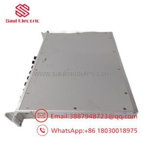
When field switches and dry contacts introduce high-frequency electrical noise or voltage surges into a control cabinet, unconditioned signal lines can destroy sensitive I/O processors. The GE IS200TBCIH2CCD acts as the primary hardware barrier within Mark VI and Mark VIe racks, terminating up to 24 discrete contact inputs while filtering out high-voltage transients.
The H2 design variant is specifically tuned for lower-voltage 24V DC excitation loops, making it an essential component for modern digital interlock networks and solid-state limit switches. Equipped with onboard metal-oxide varistors (MOVs) and high-frequency filtering capacitors, this board ensures reliable signal conditioning whether wired in a straightforward Simplex configuration or a fault-tolerant Triple Modular Redundant (TMR) architecture.
Technical Specifications
| Parameter | Specification Details |
| System Compatibility | GE Speedtronic Mark VI and Mark VIe Systems |
| Input Capacity | 24 Group-Isolated Dry Contact Inputs |
| Loop Excitation Voltage | 24 VDC Nominal (Group H2 Specification) |
| Channel Load Profile | Inputs 1–21: ~2.5 mA per point; Inputs 22–24: ~10 mA per point |
| Field Wiring Connection | 2x Removable barrier terminal blocks (TB1 & TB2, accepts up to 12 AWG wire) |
| Backplane Connectors | 3x D-sub multi-pin headers: JR1 (Simplex/TMR), JS1 (TMR), JT1 (TMR) |
| Surge Suppression | Board-mounted MOVs and RC filter networks on all input channels |
| Environmental Protection | Industrial conformal coating (CCD revision tier) |
Field Application & The “Trench” Experience
During an unplanned trip on a combined-cycle steam turbine, diagnostic logs reported simultaneous contact loss across multiple valve limit switches. Inspection revealed that an external 24V supply surge had blown several transient suppression diodes on an older terminal board. The site team pulled a fresh IS200TBCIH2CCD board from emergency stock. Because the barrier terminal strips (TB1/TB2) are removable, the instrument tech unplugged the field wiring harness intact, swapped the base circuit board onto the DIN-rail mounting, plugged the connectors back in, and restored full TMR contact monitoring without having to re-terminate 48 individual field wires.
Niche Application Scenarios:
- Turbine Trip Landings & Emergency Stop Circuits: Interfacing mechanical door interlocks, push-buttons, and pressure switch contacts to local I/O packs.
- Generator Breaker Position Monitoring: Capturing auxiliary contact state changes for high-speed sequence-of-events (SOE) logging.
- Motor Control Center (MCC) Run/Stop Feedback: Filtering noisy 24V dry-contact status lines coming from distant motor starters.
Transparency SOP: QA & Testing
- Step 1: Visual & MOV Surge Inspection — Every board undergoes 100% optical inspection of terminal block screw threads, MOV surge suppressors, and backplane connector pins to check for physical stress or thermal discoloration.
- Step 2: 24VDC Excitation Sweep — The 24V DC excitation bus is powered on a test bench to verify uniform voltage delivery across all 24 input terminals without channel-to-channel short circuits.
- Step 3: Signal Conditioning & Loopback Test — Simulated contact closures are applied across channels 1–24 while capturing output signals on JR1, JS1, and JT1 connectors to confirm clean optical pack handshaking.
- Step 4: Conformal Coating Integrity Verification — The board surface is checked under UV light to ensure full conformal coat coverage (CCD iteration) for harsh atmosphere deployment.
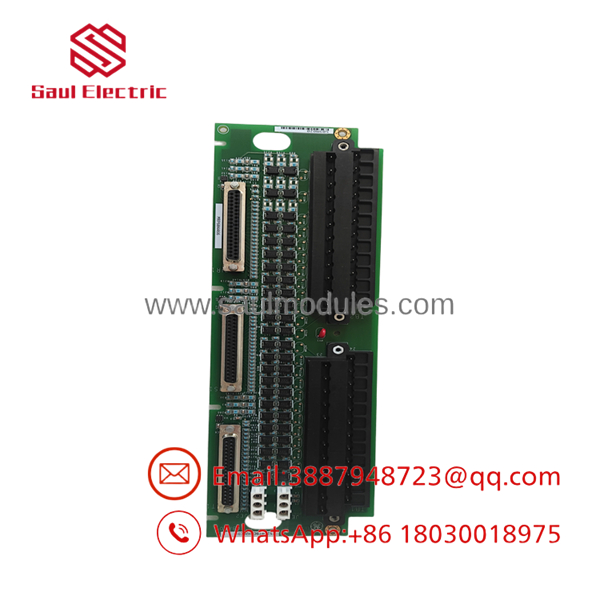
- IS200TBCIH2CCD
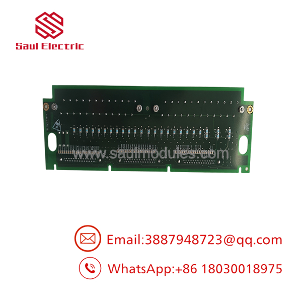
- IS200TBCIH2CCD
The Veteran’s Tech Trap Guide
- ⚠️ The H1 vs. H2 Voltage Catastrophe: Always verify the voltage rating suffix before applying power! The
H2variant is rated for 24V DC excitation. If you install anH2board into a cabinet wired for anH1(125V DC) orH3(48V DC) loop, you will instantly destroy the onboard surge filtering MOVs and blow the upstream I/O pack fuse. - PRO TIP (High-Current Channels 22–24): Channels 22, 23, and 24 draw a higher current (~10 mA) compared to Channels 1–21 (~2.5 mA). Reserve Channels 22–24 for solid-state outputs or long field wire runs where higher wetting current is necessary to keep contacts clean and prevent false open-circuit readings.
- ⚠️ TMR Cable Cabling Order: When connecting I/O packs (like PDIA or BDIA) in a Triple Modular Redundant layout, ensure cable JR1 goes to Pack A, JS1 to Pack B, and JT1 to Pack C. Crossing these cables will cause voting logic errors in your Mark VIe controller configuration.
Dynamic FAQ
Q: What is the main difference between part numbers IS200TBCIH2BCE and IS200TBCIH2CCD?
A: Both are 24V DC Contact Input Terminal Boards (TBCI Group H2). The CCD suffix represents a later hardware revision level with updated component sourcing and conformal coating iterations compared to the earlier BCE revision.
Q: Do I need to unwire field connections when replacing a damaged board?
A: No. The terminal blocks (TB1 and TB2) are two-piece removable barrier strips. You can unscrew the retention fasteners and unplug the entire wired block assembly, replace the circuit board underneath, and plug the block back in.
Q: Can this terminal board be used in both Simplex and TMR configurations?
A: Yes. For Simplex systems, connect a single I/O pack cable to header JR1. For TMR systems, connect three separate cables to JR1, JS1, and JT1 to feed identical input data to all three redundant processors.
Q: What warranty is provided with New Surplus or Refurbished TBCI units?
A: Every board passes physical inspection, voltage sweep, and channel loopback bench testing, supported by a full 12-month replacement warranty.


 Start Chat


