





Description
Technical Specifications
| Specification | 8201-HI-IS |
|---|---|
| Manufacturer | MTL Instruments |
| Series / System | MTL8000 2/1 I/O |
| Module Type | 8-channel analog input |
| Input Channels | 8 |
| Channel Configuration | Single-ended |
| Nominal Signal Range | 4–20 mA |
| Full Signal Range | 0.5–22 mA |
| HART | Pass-through; variable and status reporting |
| Field Devices | 2-wire transmitters |
| Transmitter Voltage @ 20 mA | 15 V minimum |
| Resolution | 16 bits |
| Accuracy @ 25°C | ±20 µA |
| Temperature Stability | ±0.006% of span/°C, -40°C to +70°C |
| Short-Circuit Detection | >21.5 mA |
| Open-Circuit Detection | <0.5 mA |
| Railbus Supply | 12 V |
| Railbus Current | 600 mA typical, all channels at 22 mA |
| Module Power Dissipation | 4.2 W maximum |
| Channel-to-Railbus Isolation | 60 VAC |
| Channel-to-Channel Isolation | None |
| Module Width | 42 mm |
| Weight | 260 g |
| Module Key Code | A1 |
These values are taken primarily from the MTL 8201-HI-IS product datasheet.
Intrinsic-Safety Parameters
The datasheet specifies the following safety description for each channel:
- Uo: 28 V
- Io: 93 mA
- Po: 0.65 W
- Ca: 0.14 µF
- La: 4.38 mH
The field wiring protection is specified for [EEx ia] IIC applications in the referenced documentation. Actual hazardous-area installation must be based on the applicable system certificate, entity parameters, field-device parameters, and local hazardous-area requirements.
HART and 4–20 mA Operation
The 8201-HI-IS performs two jobs on the same transmitter loop:
Primary process measurement
The 4–20 mA signal provides the process variable to the control system.
Digital HART communication
HART information can pass through the module, allowing the host system to access supported transmitter variables and status information without installing a separate HART signal path.
This makes the module useful where a plant is retaining conventional analog control architecture but still needs access to transmitter diagnostics and secondary process variables.
Field Application
Example: Hazardous-Area Pressure Transmitters
Consider an oil and gas process skid with eight 2-wire pressure and differential-pressure transmitters installed in a hazardous area.
The field loops connect to the 8201-HI-IS through the appropriate intrinsically safe field termination arrangement. The module provides the transmitter supply, measures the 4–20 mA signal, and passes HART communications toward the control system.
For commissioning, engineers should verify:
- Transmitter loop current.
- Available transmitter voltage.
- Intrinsic-safety entity parameters.
- Channel assignment.
- 4–20 mA scaling.
- HART communication status.
- Open- and short-circuit diagnostics.
The module provides at least 15 V at the transmitter at 20 mA, while its documented input impedance is approximately 350 Ω according to MTL’s technical FAQ.
Other Application Scenarios
Oil & Gas Process Instrumentation
Pressure, flow, level, and temperature transmitters located in hazardous process areas.
Chemical Processing
Analog measurement loops where intrinsic safety and HART diagnostics are required together.
Offshore and Process Platforms
High-density process instrumentation where multiple 2-wire transmitters must be integrated into a distributed I/O system.
Tank Farm Monitoring
Level and pressure transmitters requiring conventional analog measurement plus HART access.
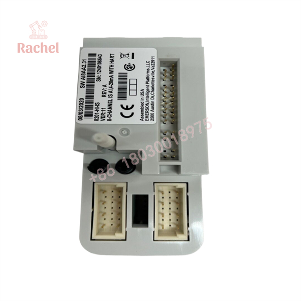
8201-HI-IS
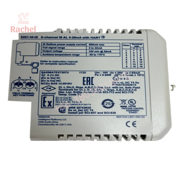
8201-HI-IS
Field Wiring & Terminal Selection
The MTL documentation specifies dedicated field-terminal options for the module:
- 8621-FT-IS — standard intrinsically safe field terminal
- 8622-FT-ISIS — intrinsically safe loop-disconnect field terminal
The field terminal is therefore part of the installation architecture and should not be treated as an arbitrary terminal block.
For an existing installation, confirm the carrier and field-terminal arrangement before ordering only the electronic module.
QA & Testing SOP
1. Identification
Verify:
- MTL Instruments marking
- Part number 8201-HI-IS
- Serial number
- Module key code
- Product revision where applicable
2. Physical Inspection
Inspect:
- Module housing
- PCB condition
- Backplane contacts
- Field connector
- Keying mechanism
- Mounting surfaces
- Signs of corrosion or contamination
3. Analog Input Test
A suitable test bench can verify representative input points such as:
- 4 mA
- 12 mA
- 20 mA
Check the reported process value against the expected engineering-unit scaling.
4. Fault Detection Test
Where supported by the test setup, verify:
- Open-loop detection
- Short-loop detection
- Channel status
- Alarm behavior
The documented thresholds are <0.5 mA for open-circuit detection and >21.5 mA for short-circuit detection.
5. HART Verification
If HART functionality is required, test communication independently from the basic analog measurement. A module that correctly reports 4–20 mA does not automatically prove that the HART communication path is functioning.
Veteran’s Tech Trap Guide
Trap 1 — 8201-HI-IS vs. 8202-HO-IS
The model numbers are easy to confuse.
- 8201-HI-IS: Analog Input
- 8202-HO-IS: Analog Output
The 8201 receives process measurements; the 8202 sends process-control output signals.
Trap 2 — Do Not Assume Channel-to-Channel Isolation
The datasheet specifies 60 VAC isolation from any channel to Railbus, but no isolation between channels in the same module. This distinction matters when engineers are evaluating grounding, common-mode conditions, and field-device arrangements.
Trap 3 — HART Does Not Replace the 4–20 mA Signal
The module’s primary process measurement remains the analog current loop. HART provides digital communication over that loop. During troubleshooting, first establish that the analog loop is correctly powered and operating before treating HART communication as the root problem.
Trap 4 — Check Transmitter Voltage Budget
The 8201-HI-IS specifies a minimum 15 V at the transmitter at 20 mA. Long cable runs, high loop resistance, barriers, and transmitter requirements can affect the available voltage. MTL also identifies the module’s approximate 350 Ω input impedance.
Procurement & Replacement Notes
For a replacement 8201-HI-IS, verify the complete installation rather than matching only the part number:
- Existing MTL8000 system architecture
- Carrier type
- Field-terminal model
- Module keying
- 2-wire transmitter requirements
- Hazardous-area certification
- HART requirements
- Existing Railbus/BIM configuration
MTL’s documentation index currently lists 8201-HI-IS within the MTL8000 documentation family.
One secondary distributor currently labels the part as discontinued, but that should be treated as a distributor inventory statement rather than definitive manufacturer lifecycle status; the official MTL documentation index still identifies the 8201-HI-IS product code.
FAQ
What is the MTL 8201-HI-IS?
It is an 8-channel intrinsically safe analog input module for 4–20 mA signals with HART functionality, intended primarily for 2-wire transmitters.
How many channels does the 8201-HI-IS have?
It has 8 single-ended analog input channels.
Does the 8201-HI-IS support HART?
Yes. It provides HART pass-through plus HART variable and status reporting.
What is the resolution?
The documented resolution is 16 bits. Accuracy at 25°C is specified as ±20 µA.
Is the 8201-HI-IS intrinsically safe?
Yes. It is specifically designed with intrinsically safe field circuits. The applicable hazardous-area installation must nevertheless be engineered according to the module certificate, entity parameters, field-device parameters, and installation requirements.
What should be checked when buying New Surplus 8201-HI-IS?
Request photographs of the actual module and verify the exact 8201-HI-IS marking, serial information, physical condition, connector/keying condition, and packaging. If functional testing is claimed, ask whether the test included 4–20 mA measurement, fault detection, and HART communication. “New Surplus” should be treated as an inventory-condition description rather than proof of current factory-new production.

 Start Chat


