





Description
Product Introduction
The NK Technologies AG1-SDT1-24U-DEN-A55 is a precision, solid-core ground fault sensor designed to protect personnel, equipment, and industrial automation systems against low-level current leakage to ground. By routing all current-carrying conductors (phase and neutral) through its internal sensing aperture, the AG1 vectorially sums the currents to detect insulation breakdowns and ground loops as low as 55 mA.
This specific model features a universal 24V AC/DC power supply input and a De-energized (DEN) output configuration. In DEN mode, the output relay remains unenergized during normal system operations and changes state only when a ground fault exceeding 55 mA is detected or power is removed. It provides electro-mechanical SPDT dry contacts for seamless integration into PLC digital inputs, safety relays, or audible alarm circuits.
Key Technical Specifications
| Parameter | Value |
| Manufacturer | NK Technologies |
| Series | AG Series (Ground Fault / Earth Leakage) |
Trip Point (-A55) |
55 mA fixed threshold |
Output Type (-SDT1) |
Single Pole Double Throw (SPDT) Relay (1A @ 125V AC, 2A @ 30V DC) |
Output State (-DEN) |
De-energized on Normal (Relay energizes on fault detection) |
Supply Voltage (-24U) |
24V AC/DC (+10\% / -15\%) |
| Response Time | \le 50 ms at 100 mA fault; \le 20 ms at 500 mA fault |
| Enclosure / Aperture | Solid-Core chassis, 0.74 inch (19 mm) diameter aperture |
| Mounting Type | DIN-rail or flat panel mounting chassis |
| Operating Temperature | -20^\circC to +50^\circC (-4^\circF to 122^\circF) |
Application Scenarios & The “Trench” Experience
In industrial washdown facilities, electric heating banks, and submersible pump skids, moisture ingress or cable degradation continuously threatens to cause ground faults. A undetected micro-leakage current will gradually erode motor windings, trip main upstream breakers unexpectedly, or pose severe shock hazards to technicians. Installing an AG1-SDT1-24U-DEN-A55 directly at the equipment branch circuit allows maintenance teams to isolate ground faults locally at 55 mA before the fault escalates into a destructive high-energy short circuit or trips an entire main distribution panel.
- Electric Heat Tracing & Heating Elements – Monitoring industrial freeze-protection heat cables for insulation breakdown due to thermal expansion.
- Submersible Pumps & Pumping Rigs – Detecting water ingress into motor housings before winding short-circuits destroy the pump.
- Personnel Protection Systems – Providing earth leakage detection in wet industrial environments, washdown areas, and food processing lines.
- PLC Safety Interlock Racks – Providing clean dry-contact inputs to DCS / PLC racks to trigger shutoff valves during earth leakage events.
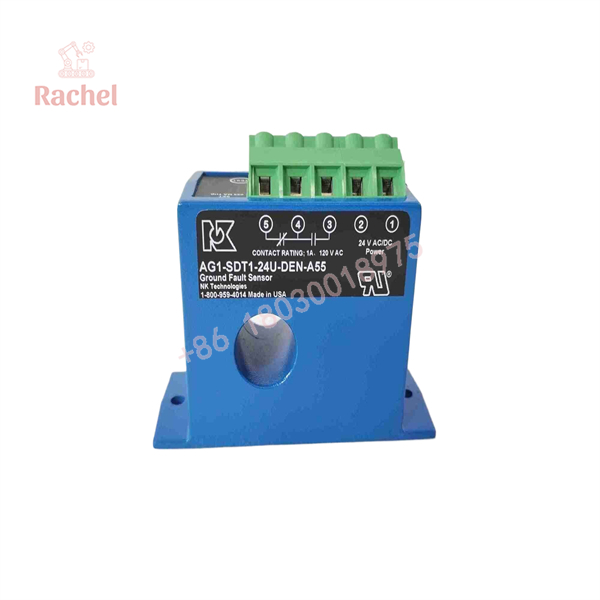
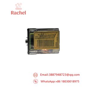
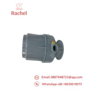
AG1-SDT1-24U-DEN-A55
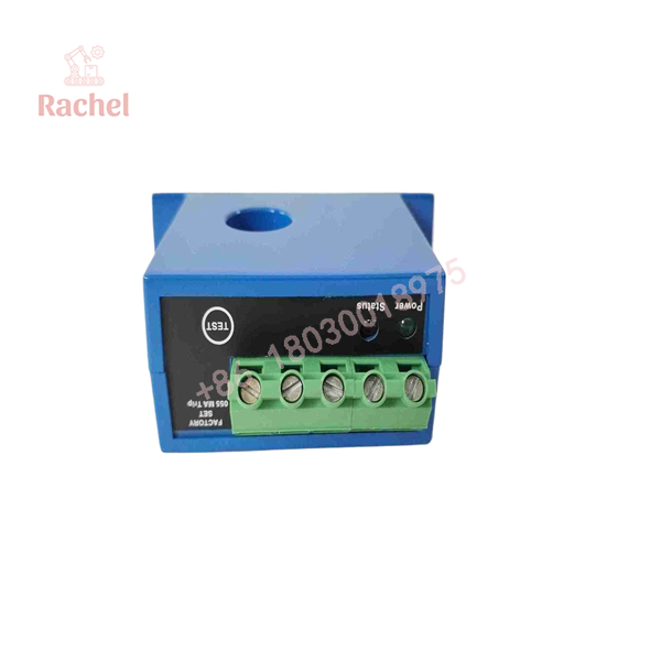
AG1-SDT1-24U-DEN-A55
Transparency SOP: Quality Assurance & Testing
Every surplus or refurbished NK AG1-SDT1-24U-DEN-A55 sensor undergoes a rigorous 5-stage bench test protocol prior to dispatch:
- Inbound Physical Audit: Visual inspection of housing plastics, terminal block screws, aperture interior, and DIN-rail mounting clips.
- Power Supply & Voltage Rail Test: Powered continuously at 24V AC and 24V DC to verify internal regulator stability and LED status behavior.
- Calibrated Fault Current Injection: Primary wire routed through the aperture and energized with precision micro-amp current generators; verified exact trip pick-up at 55 mA \pm 5\%.
- Relay Contact Continuity Test: SPDT contacts bench-tested under 24V DC switching loads; verified zero contact resistance across NO/NC pins during fault actuation.
- Reset & Latch Logic Verification: Tested under auto-reset and manual latching wiring configurations; cleared test parameters and packaged in ESD shielding.
The Veteran’s Tech Trap Guide (Crucial Value-Add)
⚠️ Pass ALL Current-Carrying Wires Through the Window: You MUST route all phase (L1, L2, L3) AND neutral wires through the sensor’s aperture. Do NOT pass the ground (PE) conductor through the sensor. If you miss a neutral wire or include the green ground wire, vector cancelation fails and the sensor will false-trip immediately upon load connection.
❗ Understand the -DEN vs -EN Relay State:
DEN(De-energized on Normal): The relay coil is OFF during normal operation and energizes during a fault. Use this mode when you want an alarm to turn ON during a ground fault.EN(Energized on Normal): The relay coil is ON during normal operation and drops out on a fault or loss of 24V supply power (fail-safe mode). Verify your control logic match before installation.
⚠️ Do NOT Use on Variable Frequency Drive (VFD) Outputs: Standard AG1 ground fault sensors are calibrated for 50/60 Hz sine waves. Connecting the sensor to the output side of a VFD will cause false tripping due to high-frequency carrier noise and capacitive leakage currents. Always install the sensor on the line side (input) of the drive or use VFD-rated ground fault models.
❗ Observe Wire Diameter Constraints: Ensure the total bundle outer diameter of all power cables passing through the sensor is under 0.74 inches (19 mm). Forcing tightly wrapped thick cables into the aperture can fracture the internal ferrite core, permanently ruining sensor accuracy.
Frequently Asked Questions (FAQ for Conversion)
Q: What does the suffix 24U mean in the part number?
A: The 24U suffix indicates a universal 24V AC/DC power supply requirement (20.4–26.4V AC/DC), allowing the sensor to be powered by standard industrial 24V DC panel power supplies or 24V AC control transformers.
Q: Can this sensor be set to latch open after a ground fault occurs?
A: Yes. The AG1 series supports both automatic reset and latching functionality depending on how the control wiring is jumpered at the terminal block. In latching mode, once a 55 mA fault is detected, the relay stays tripped until power is cycled or the reset loop is opened.
Q: Is the 55 mA trip point adjustable on this model?
A: No. Model code -A55 signifies a factory-set, fixed trip point of 55 mA. If you require an adjustable trip range (e.g., 5–100 mA), you would need the adjustable AG1-SDT1-24U-DEN-TRP variant.
Q: What is the warranty on this sensor?
A: All our new surplus and bench-tested NK Technologies sensors come backed by a full 12-month direct replacement warranty. If the unit fails under standard operating conditions within one year, we replace it immediately from stock.

 Start Chat


