





Description
Product Introduction & Engineering Value
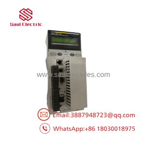
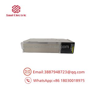
The 140DDI35300 is a high-density digital input card for Quantum systems where field devices operate from a 24 VDC control supply. With 32 inputs, it can consolidate proximity sensors, auxiliary contacts, pushbuttons, limit switches, relay feedback, and equipment-status signals into a single Quantum I/O slot.
The electrical details matter during replacement. The module accepts a defined 19.2–30 VDC operating range, while its input threshold and current characteristics determine whether marginal field signals are correctly interpreted. Schneider documentation also identifies input isolation and short-circuit protection characteristics that should be considered when diagnosing a problematic channel.
Technical Specifications
| Parameter | Specification |
|---|---|
| Catalog Number | 140DDI35300 |
| Platform | Modicon Quantum |
| Module Type | Discrete DC input |
| Number of Inputs | 32 |
| Nominal Input Voltage | 24 VDC |
| Operating Voltage Range | 19.2–30 VDC |
| Input Groups | 4 groups of 8 |
| Addressing Requirement | 2 input words |
| Input Current | Approximately 6 mA per channel |
| Input Impedance | Approximately 4 kΩ |
| State 1 Threshold | ≥15 VDC |
| State 0 Threshold | ≤5 VDC |
| Input Isolation | 1500 Vrms |
| Response Time | Approximately 0.2 ms ON / 0.3 ms OFF |
| Bus Current | Approximately 200 mA |
| Power Dissipation | Approximately 1.5 W |
| Operating Temperature | 0–60°C |
| Storage Temperature | -40–85°C |
| Humidity | Up to 95% non-condensing |
| Module Weight | Approximately 0.3 kg |
The key electrical point is the 15 VDC ON threshold and 5 VDC OFF threshold. A field circuit sitting between those limits should not be treated as a healthy digital signal simply because a handheld meter shows voltage.
Field Application & the “Trench” Experience
A packaging line has several remote machine-control signals feeding a Quantum rack. One proximity sensor intermittently reports OFF even though the sensor’s indicator remains lit.
The maintenance technician measures the sensor output at the input terminal and initially sees roughly 18 VDC. That sounds acceptable.
It is not enough to stop there.
The technician checks the voltage under load, verifies the common reference, inspects the terminal connection, and compares the affected channel against neighboring inputs. A voltage drop caused by a damaged conductor or poor connection can produce a signal that appears reasonable with no load but becomes marginal when connected to the PLC input.
The 140DDI35300’s individual channel LEDs then provide a useful second indication: is the module actually recognizing the field signal?
Specific application scenarios:
- Packaging machinery: photoelectric sensors, limit switches, guard feedback, and machine interlocks.
- Pump and compressor control: run feedback, fault contacts, pressure-switch status, and permissives.
- Conveyor systems: proximity sensors, belt switches, motor auxiliary contacts, and emergency-status signals.
- Water-treatment panels: valve-position feedback, pump status, and high/low level switches.
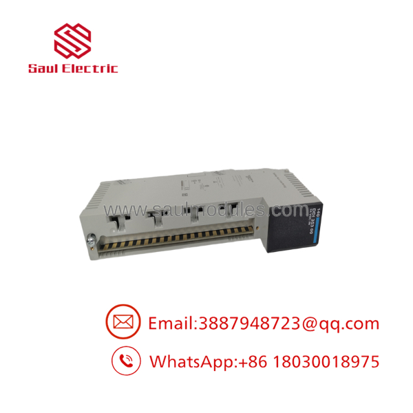
140DDI35300
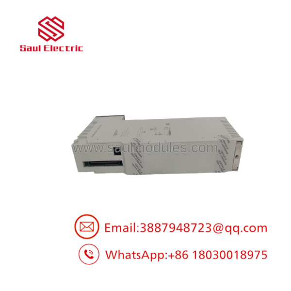
140DDI35300
Transparency SOP: QA & Testing
For New Surplus or refurbished 140DDI35300 stock, testing should cover both the 24 VDC input circuitry and the Quantum backplane interface.
- Verify identification — Confirm
140DDI35300on the actual module label. - Inspect the hardware — Check the housing, terminal interface, LEDs, backplane connector, and labeling.
- Power the module — Install it in an appropriate Quantum test rack.
- Apply controlled DC signals — Use a regulated 24 VDC source and suitable protected test fixture.
- Exercise representative channels — Confirm OFF/ON transitions across all four input groups.
- Verify threshold behavior — Confirm that representative signals produce the expected PLC input state.
- Check diagnostics — Verify individual input LEDs and module status indication.
- Verify PLC communication — Confirm that the controller correctly reads the input word states.
- Document results — Record tested channels, test conditions, and final stock condition.
A good test report should say more than “tested OK.” For a 32-point input card, channel-level or representative-channel test information is considerably more useful to the buyer.
The Veteran’s Tech Trap Guide
⚠️ Trap #1 — Don’t confuse 24 VDC nominal with 24 VDC guaranteed at every condition.
The published operating range is 19.2–30 VDC, but the module’s logic thresholds are different. A signal must reach the specified ON threshold to be reliably interpreted as ON.
⚠️ Trap #2 — Check the common/reference wiring.
A perfectly healthy sensor can appear dead to the PLC when its 0 V reference is missing or incorrectly routed. Before replacing the input module, measure both the signal and its reference at the actual module terminals.
PRO TIP: Measure voltage at the I/O module, not only at the field device. Those two measurements can tell very different stories.
⚠️ Trap #3 — Watch for marginal signals.
A sensor output that drops close to the input threshold during machine operation can create intermittent PLC faults. Check the signal while the connected equipment is operating rather than relying solely on a static bench measurement.
⚠️ Trap #4 — Don’t assume a newer 32-point module is automatically equivalent.
Replacement selection should account for input type, commoning arrangement, polarity, diagnostics, isolation, wiring system, and Quantum-to-new-platform migration requirements. Matching “32 inputs, 24 VDC” is only the starting point.
Dynamic FAQ
Q: What is the Schneider 140DDI35300?
A: It is a 32-channel 24 VDC discrete input module for the Modicon Quantum PLC platform.
Q: How many inputs does the 140DDI35300 provide?
A: It provides 32 DC discrete inputs, arranged in four groups of eight and addressed across two input words.
Q: What voltage does the 140DDI35300 use?
A: Its nominal input voltage is 24 VDC, with a published operating range of approximately 19.2–30 VDC.
Q: What should I check if one input stays OFF?
A: Measure the signal directly at the module terminal, verify the 0 V reference, inspect field wiring and terminal connections, compare the voltage against the input threshold, and check the individual channel LED before replacing the module.
Q: Is the 140DDI35300 discontinued?
A: Yes. Schneider Electric currently lists the 140DDI35300 as a discontinued Modicon Quantum product.
Q: How should New Surplus 140DDI35300 stock be verified?
A: Verify the exact catalog number, inspect all connectors and indicators, and request evidence of controlled 24 VDC functional testing. For a 32-channel module, ask whether all inputs or a defined representative set were tested. The supplier should also provide the stock condition, warranty period, and return terms in writing.

 Start Chat


