





Description
Product Introduction & Engineering Value
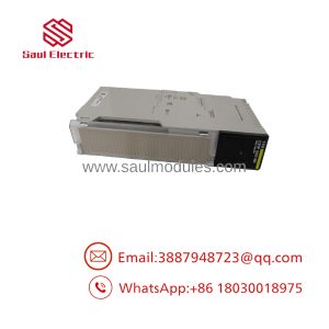
The 170AAI03000 handles the conversion between standard industrial 4–20 mA transmitter signals and the Momentum controller. Eight channels provide a relatively high I/O density for process instrumentation, making the module suitable for compact control panels where several analog measurements must be collected at one I/O location.
The practical concern during replacement is signal scaling. The module converts the electrical current into a digital value, but the PLC application determines how that value represents engineering units. A replacement should therefore be checked at both levels: electrical input performance and application-level scaling.
Technical Specifications
| Parameter | Specification |
|---|---|
| Catalog Number | 170AAI03000 |
| Platform | Modicon Momentum |
| Module Type | Analog input |
| Number of Inputs | 8 |
| Input Signal | 4–20 mA |
| Input Configuration | Current |
| Resolution | 12-bit |
| Input Isolation | Channel/commoning arrangement should be verified against the installed revision |
| Typical Application | 2-wire/4-wire transmitter signals |
| Conversion | Analog-to-digital |
| Signal Processing | PLC-readable digital input values |
| Installation | Momentum I/O base |
| Application | Process instrumentation and analog feedback |
Important procurement note: Published third-party specifications for legacy Momentum modules are not always consistent on secondary electrical details. For a direct replacement, verify the exact hardware revision and original Schneider documentation rather than relying on a reseller’s abbreviated specification table.
Field Application & the “Trench” Experience
A water-treatment skid uses several 4–20 mA transmitters to monitor discharge pressure, tank level, differential pressure, and flow. One analog channel suddenly reads an implausible value.
The technician checks the transmitter first. Its local display is normal.
Next comes the loop.
The current is measured directly at the Momentum input terminals. Instead of the expected approximately 12 mA, the loop is producing a substantially different value. That immediately changes the troubleshooting path: the transmitter, loop power, wiring, and input channel all need to be separated as possible fault sources.
A useful practice with 4–20 mA systems is to document the actual loop current before replacing the analog card. A software value of “75%” does not tell you whether the fault originates in the transmitter, wiring, scaling, or A/D conversion.
Specific application scenarios:
- Tank level measurement: 4–20 mA level transmitters feeding closed-loop control.
- Pump skid monitoring: pressure and flow transmitter inputs.
- HVAC/process utilities: differential-pressure and temperature transmitter signals.
- Chemical dosing systems: flow and pressure feedback for metering pumps.
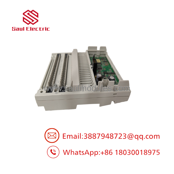
170AAI03000
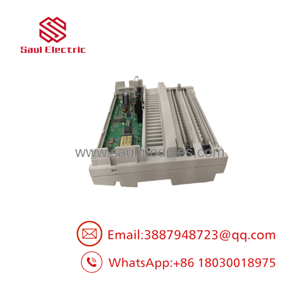
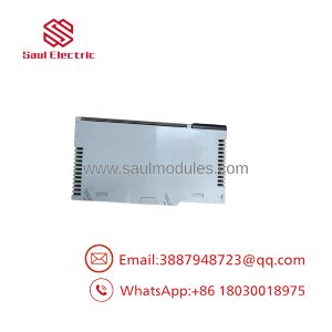
170AAI03000
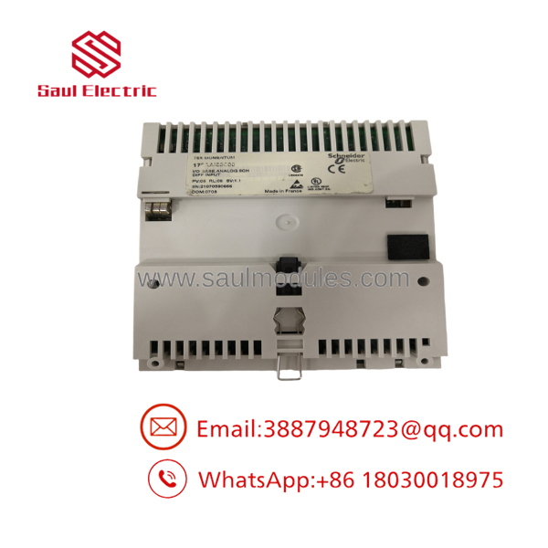
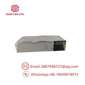
170AAI03000
Transparency SOP: QA & Testing
For New Surplus or refurbished 170AAI03000 inventory, the test should use calibrated current simulation rather than simply powering the module.
- Verify the catalog number — Confirm
170AAI03000on the module label. - Inspect the hardware — Check the housing, connector interface, terminals, and labeling.
- Install on a compatible Momentum base — Confirm the module is recognized by the control system.
- Apply a controlled current signal — Use a calibrated source appropriate for the input range.
- Check low point — Verify the expected digital value at 4 mA.
- Check midrange — Test a representative value such as 12 mA.
- Check high point — Verify the response at 20 mA.
- Exercise all channels — Repeat the test across the eight inputs where the test fixture permits.
- Verify application scaling — Confirm the PLC converts the raw input into the expected engineering value.
- Document results — Record the test equipment, input current, channel results, and stock condition.
PRO TIP: For an analog module, “all LEDs normal” is not a meaningful functional test. The A/D conversion path needs to be exercised with known current values.
The Veteran’s Tech Trap Guide
⚠️ Trap #1 — Don’t diagnose a transmitter from the PLC value alone.
If the PLC displays an abnormal pressure or flow value, measure the actual mA loop current at the input. That separates a field-loop problem from an analog-input problem much faster.
⚠️ Trap #2 — 4 mA is not necessarily “zero” in the process application.
A standard 4–20 mA transmitter uses 4 mA as the lower end of its calibrated range. The PLC’s engineering-unit scaling determines what that value represents.
PRO TIP: Preserve the original scaling parameters before replacing the hardware. A perfectly functioning replacement module can still produce incorrect process values if the application scaling is changed.
⚠️ Trap #3 — Check loop power and transmitter wiring.
A 2-wire transmitter depends on the current loop for both signal and power. A wiring problem can produce symptoms that look like a failed analog input.
⚠️ Trap #4 — Don’t assume every eight-channel Momentum analog module is interchangeable.
Channel count alone is not enough. Verify input signal type, current/voltage range, wiring arrangement, resolution, isolation, Momentum base compatibility, and application configuration before approving a substitute.
Dynamic FAQ
Q: What is the Schneider 170AAI03000?
A: It is a Modicon Momentum eight-channel analog input module intended for industrial analog-current signals, commonly used with 4–20 mA instrumentation.
Q: How many analog inputs does the 170AAI03000 provide?
A: The module provides 8 analog input channels.
Q: What signal should be applied to the 170AAI03000?
A: It is designed for 4–20 mA current input signals. Confirm the exact hardware revision and field wiring requirements before commissioning a replacement.
Q: What should I check when an input value is incorrect?
A: Measure the actual loop current at the module, then check transmitter power, wiring polarity, loop resistance, channel configuration, raw A/D value, and PLC engineering-unit scaling.
Q: Can I replace the 170AAI03000 with another Momentum analog module?
A: Not without checking compatibility. The replacement must match the signal type, channel architecture, electrical characteristics, Momentum base, and application configuration. For a legacy control system, an exact part-number replacement is generally the lower-risk approach.
Q: How should New Surplus 170AAI03000 stock be verified?
A: Confirm the exact part number and hardware condition, inspect the connector and housing, install it on a compatible Momentum base, and test the analog channels with calibrated 4–20 mA signals. The supplier should identify the unit as New Surplus, Used, or Refurbished and state the warranty and return terms clearly.

 Start Chat


