





Description
Product Introduction & Engineering Value
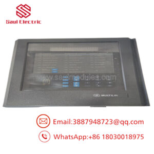
The GE Multilin SR489-P5-HI-A20-E is a digital generator management relay engineered for primary protection and control of small to medium-sized synchronous or induction generators operating at 50/60 Hz. Unlike motor relays (like the 469 series), the 489 is tailored specifically for generator-specific protection schemes, including generator stator differential, reverse power/directional power (ANSI 32), loss of excitation (ANSI 40), and 100% stator earth fault detection.
By integrating thermal monitoring, electrical protection functions, generator metering, and event logging into a single draw-out assembly, the SR489 eliminates the need for separate discrete protection devices. The E designation provides an enhanced front panel interface with a high-visibility LCD display and localized target LEDs for clear, real-time diagnostic visibility right at the switchgear door.
Part Number Decoder & Hardware Specs
Order Code Breakdown: SR489 - P5 - HI - A20 - E
SR489: Base Series (Multilin 489 Generator Management System)P5: Phase Current Inputs — 5A CT SecondariesHI: Power Supply — 90–300 VDC / 70–265 VAC high-voltage control busA20: Analog Outputs — 4x 4–20 mA (or 0–20 mA / 0–1 mA) assignable outputsE: Display Option — Enhanced Front Panel interface with multi-line LCD display
Key Technical Specifications
- Core Generator Protection Elements:
- Generator Stator Differential (ANSI 87G)
- Reverse Power / Anti-Motoring (ANSI 32R) & Low Forward Power (ANSI 32L)
- Loss of Excitation / Underexcitation (ANSI 40)
- Overexcitation / Volts per Hertz (ANSI 24)
- Negative Sequence Overcurrent / Unbalance (ANSI 46)
- Phase Distance / Backup Protection (ANSI 21G)
- RTD Inputs: 12 assignable 3-wire RTD inputs (100-ohm Pt, 120-ohm Ni, 100-ohm Ni, or 10-ohm Cu)
- Digital Inputs: 9 optically isolated assignable contact inputs
- Output Relays: 6 output relays (Trip, Alarm, Auxiliary, and Inhibit functions)
- Communication Ports: 2x Rear RS485 Modbus RTU ports + 1x Front RS232 programming port
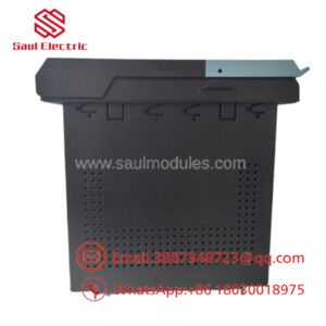
- Enclosure: Standard 3/8-size 19-inch rack ratio draw-out case with automatic shorting CT bars
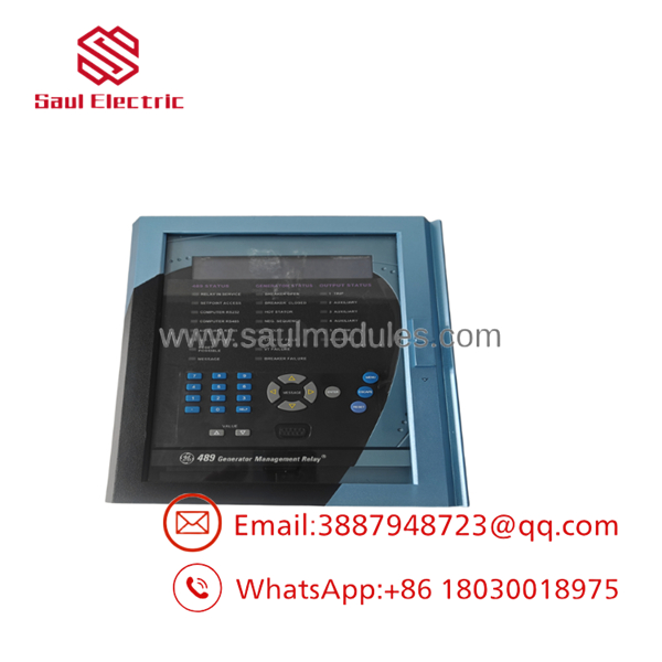
- SR489-P5-HI-A20-E
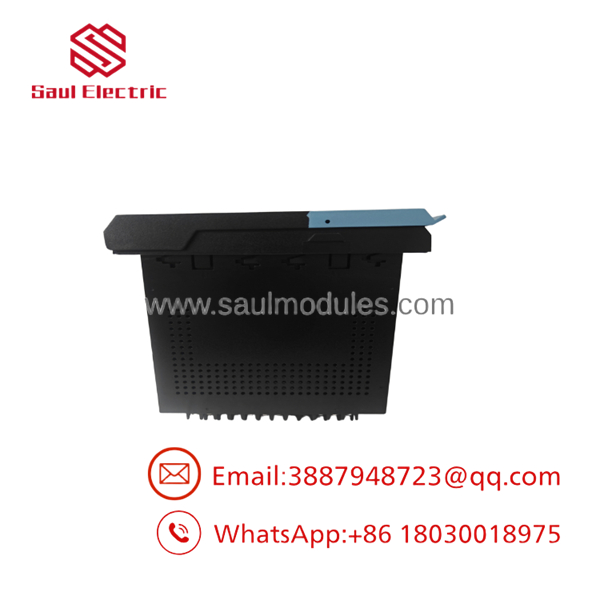
- SR489-P5-HI-A20-E
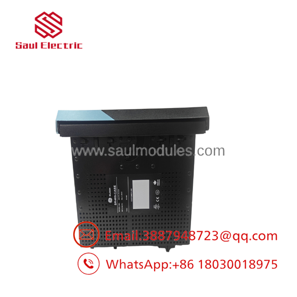
- SR489-P5-HI-A20-E
Field Application & The “Trench” Experience
During an overhaul at a municipal co-generation plant, operators experienced nuisance trips on a 5MW steam-turbine generator driven by reverse-power conditions during grid synchronizations. The existing electromechanical reverse power relay lacked precise time-delay adjustments.
The plant installed an -P5-HI-A20-E. Wired directly into 5A main phase CTs (P5) and powered off the station’s 125 VDC battery system (HI), the 489 relay allowed engineers to configure accurate anti-motoring trip limits with custom time delays via software. The enhanced front panel (E) provided immediate visibility of real-time active power (kW), reactive power (kVAR), and power factor, while the 4–20 mA analog outputs (A20) streamed power measurements directly into the DCS.
Niche Application Scenarios:
- Industrial Co-Generation Plants: Paralleling embedded gas/steam turbine generators with utility grids.
- Emergency Diesel Generator Sets: Providing backup generator overcurrent, reverse power, and loss of excitation protection.
- Hydroelectric Facilities: Managing low-speed hydro generator thermal modeling, bearing RTD limits, and voltage/frequency interlocks.
Transparency SOP: QA & Testing
- Draw-Out Mechanism & CT Shorting Inspection: The outer chassis contacts, draw-out release latches, and rear shorting springs are physically verified to ensure proper CT shorting during module extraction.
- High-Voltage Auxiliary Power Ramp: The
HIpower supply card is tested across 70–265 VAC and 90–300 VDC to verify stable bootup and logic power distribution. - 5A Secondary Injection Testing: Balanced 5A secondary current signals are applied across phase and differential CT inputs to verify metering accuracy and differential pickup (87G) thresholds within ±0.5%.
- Reverse Power & Voltage Injection Test: Combined current and voltage signals are injected using a 3-phase relay test set to test directional power elements (ANSI 32) and Volts/Hertz (ANSI 24) timing curves.
- Analog Output Loop Verification: All four 4–20 mA analog output channels (
A20) are driven under forced test software conditions to confirm linear current output response.
The Veteran’s Tech Trap Guide
- ⚠️ SR469 (Motor) vs. (Generator) Software Keying: Although the physical outer draw-out cases for the 469 and 489 look identical, the internal software algorithms and protection curves are completely different. You cannot plug an inner module into an SR469 case pre-wired for motor logic without re-verifying full terminal mapping and functional settings.
- PRO TIP (Volts per Hertz Calibration): When commissioning the ANSI 24 (Volts/Hertz) protection element on step-up transformer units, ensure your VT ratio settings in the 489 match actual primary line voltages. Improper VT setup will trigger premature V/Hz trips during routine generator startup ramping.
- ⚠️ Reverse Power Trip Delay Tuning: When setting the anti-motoring element (ANSI 32), set a slight time delay (typically 2–5 seconds) to prevent false trips caused by power swings during transient grid synchronizations.
Dynamic FAQ
Q: What is the main difference between a GE SR469 and a GE relay?
A: The SR469 is designed specifically for motor protection (focusing on thermal overload curves, stall protection, and start-inhibits), while the is tailored for generator protection (featuring generator differential 87G, reverse power 32, loss of excitation 40, and 100% stator ground fault protection).
Q: What CT secondary rating is required for the -P5-HI-?
A: The P5 code indicates that this module requires 5A CT secondaries on its phase current inputs.
Q: What power supply range does the HI hardware code support?
A: The HI power supply operates on high-voltage control buses accepting 90 to 300 VDC or 70 to 265 VAC.


 Start Chat


