





Description
Core Product Summary
The Terasaki ERB-112 is a marine-grade residual current earth fault protection relay designed to monitor low-voltage AC power distribution systems and detect insulation breakdown or current leakage in vessel circuits. Built for integration into Terasaki marine switchboards and main distribution panels, the unit continuously evaluates current transformer (CT) input signals to safeguard shipboard generators, motors, and auxiliary machinery against earth leakage hazards.
Operating on a dual AC supply voltage of 100 V or 220 V at 50/60 Hz, the relay features a fixed earth fault trip setting of 12 A residual leakage current. When an insulation fault exceeds the threshold, the unit executes an instantaneous trip within 80 milliseconds at 1.5 times the rated fault current, energizing two SPST auxiliary contact outputs rated at 5 A / 250 VAC. The front panel incorporates a latching red fault LED, a manual reset button, and an integrated functional test button to allow routine verification of protection logic without inducing actual line faults.
Key Technical Specifications
| Specification | Verified Value / Parameter |
| Brand / Manufacturer | Terasaki Electric |
| Product Series | ERB Series Marine Earth Fault Relays |
| Model Number | ERB-112 |
| Product Function | Marine residual current earth fault protection relay |
| Rated Supply Voltage | AC 100 V / 220 V (dual supply compatible, 50/60 Hz) |
| Fixed Trip Threshold | 12 A residual leakage current |
| Operating Trip Time | Instantaneous ≤ 80 ms (at 1.5× rated fault current) |
| Minimum Detectable Current | 20% of fixed 12 A setting (2.4 A) |
| Output Contact Rating | 2 SPST contacts, 5 A / 250 VAC (resistive load) |
| Compatible Zero-Sequence CT Ratios | 300/5, 500/5, 800/5 |
| Dielectric Strength | 2 kV AC for 1 minute (signal circuits) |
| Mechanical Contact Life | 5,000,000 switching cycles under rated resistive load |
| Front Panel Indications & Controls | Red fault indicator LED (latched), manual test button, manual reset button |
| Operating Temperature | -10 °C to +50 °C |
| Front Protection Class | IP30 |
| Standard Compliance | IEC 60945 (Marine Electrical Standard); NK, DNV, ABS marine class certified |
Detailed Product Overview
The Terasaki ERB-112 plays a vital role in vessel safety automation by continuously supervising electrical insulation integrity across AC distribution systems. On ships and offshore platforms, ungrounded or high-resistance grounded low-voltage networks can experience phase-to-earth leakage due to cable insulation degradation, moisture ingress, or motor winding failures. The ERB-112 isolates these fault conditions before they escalate into destructive double-line-to-ground short circuits or fire hazards.
The module interfaces with secondary windings of zero-sequence current transformers (ZCT) installed around primary distribution conductors. Under normal operating conditions, the vector sum of three-phase currents equals zero. When an earth leakage path develops, the resulting unbalanced residual current induces a secondary signal in the CT. The ERB-112 processes this analog signal against its calibrated 12 A fixed threshold. Upon reaching trip condition, the internal circuit latches the alarm state, illumination LED, and output contacts within 80 milliseconds.
Designed specifically for demanding marine environments, the relay housing incorporates internal surge filtering to withstand electrical transients caused by heavy propulsion drives, generators, and inductive switching. System operators can perform mandatory pre-voyage safety checks using the front-panel manual test pushbutton, which injects a internal test signal to verify sensor processing and trip relay actuation.
Dimensions, Mounting & Connection Notes
- Mounting Method: Mounts on standard 35 mm DIN rail or directly within Terasaki marine switchboard terminal bays using integrated locking clips.
- Wiring Isolation: Separate, dedicated terminal wiring zones are provided for AC auxiliary supply lines, CT secondary signal inputs, and relay output contacts.
- CT Circuit Safety: Never open-circuit the secondary terminals of an energized current transformer during maintenance to prevent dangerous high-voltage generation.
- Environmental Restrictions: Designed with IP30 front-panel ingress protection. Mount inside a sealed, IP-rated control cabinet when deployed in areas subject to continuous saltwater spray or high humidity.
- Dielectric Testing: Disconnect external signal cabling and power inputs before conducting high-voltage megohmmeter insulation resistance tests on connected distribution buses.
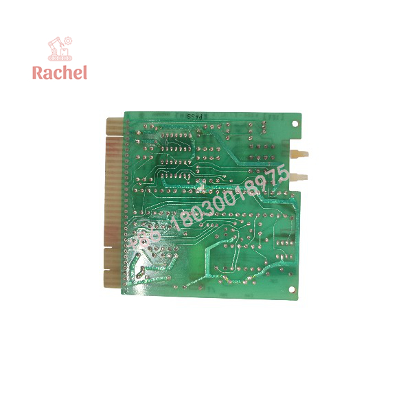
ERB-112
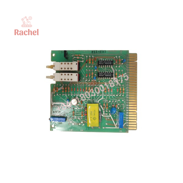
ERB-112
System Compatibility & Integration Requirements
| Item / Dependency | Verified Compatibility or Requirement | Practical Note |
| Switchboard System | Terasaki AC low-voltage marine distribution panels | Compact DIN rail enclosure for panel mounting |
| Power Supply Circuit | Dedicated, filtered AC 100 V or 220 V (50/60 Hz) line | Connect to stable auxiliary distribution supply to prevent spurious trips |
| Current Transformer | Marine zero-sequence CTs with 300/5, 500/5, or 800/5 ratio | Connect CT secondary directly to designated input terminals |
| Output Interfacing | Trip coils, master alarm loops, or safety PLC digital inputs | Relay contacts rated for 5 A / 250 VAC |
| Grounding Standard | Vessel protective ground bus | Connect unit enclosure ground terminal via 2.5 mm² copper grounding conductor |
FAQ
What is the primary function of the Terasaki ERB-112?
The Terasaki ERB-112 is a marine-grade residual current relay designed to detect insulation breakdown and earth leakage faults in low-voltage AC shipboard power circuits.
What is the trip threshold and response speed of the ERB-112?
It features a fixed earth fault trip setting of 12 A residual current with an instantaneous trip response time of 80 milliseconds or less at 1.5 times the rated fault current.
What power supply voltages are compatible with this module?
The ERB-112 is dual-voltage compatible, operating on AC 100 V or AC 220 V power supplies at 50/60 Hz.
Which current transformers work with the ERB-112?
The relay is compatible with marine zero-sequence current transformers (ZCT) utilizing secondary output ratios of 300/5, 500/5, or 800/5.
How is a fault cleared after the relay trips?
Once an earth fault triggers the relay, the front-panel red LED and output contacts remain latched until an operator manually presses the front-panel reset pushbutton after fixing the underlying fault.
How can operators verify that the protection circuit is functioning?
Pressing the front-panel manual test pushbutton injects an internal test signal into the monitoring logic to confirm full circuit operation without creating a real earth fault on the power grid.
Documented Performance Data
| Metric | Value / Range | Operating Condition |
| Operating Trip Time | ≤ 80 ms | Measured at 1.5× rated fault current |
| Minimum Detectable Current | 2.4 A (20% of setting) | Baseline residual threshold detection |
| Relay Contact Life | 5,000,000 cycles | Rated resistive load (5 A / 250 VAC) |
| Dielectric Strength | 2,000 VAC for 1 minute | Between signal terminals and ground |


 Start Chat


