





Description
Product Introduction & Engineering Value
Managing 115V high-voltage field contact inputs in high-availability safety loops requires hardware that can filter severe electrical noise without slowing down execution time. The Triconex 3501TN2 enhanced digital input module brings 32 non-commoned 115V AC/DC field signals directly into the Tricon Triple Modular Redundant (TMR) processing framework.
Instead of routing field signals through single-channel optocouplers, the 3501TN2 splits every discrete point across three isolated internal legs. Three onboard microprocessors independently filter, debounce, and diagnose field states before transmitting data across the TriBus backplane. This guarantees that a failed optocoupler or field short never triggers a false emergency trip or blinds your SIS to a true process shutdown condition.
Technical Specifications
| Parameter | Specification |
| Input Points | 32 points (non-commoned, point-to-point isolated) |
| Nominal Voltage | 115 VAC / VDC |
| Operational Voltage Range | 90 to 155 VAC / VDC |
| Frequency Range | DC or 47 to 63 Hz |
| OFF to ON Threshold | >86 VAC / VDC |
| ON to OFF Threshold | <28 VAC / VDC |
| Turn-On Current (Nominal) | 6 to 9 mA |
| Input Delay Time | OFF to ON: <8 ms |
| Point-to-Point Isolation | >1500 VDC |
| Power Dissipation | 1.5 W per ON channel (2.9 W max at full field voltage) |
| Diagnostic Features | Continuous channel self-test, Stuck-ON contact detection, TriBus health checking |
Field Application & The “Trench” Experience
The Trench Story
A Midwest power generation plant experienced intermittent channel faults on a main boiler safety interlock rack during peak summer dispatch. The installed digital input card started reporting transient diagnostic alarms due to high thermal cycles inside the local control panel. System engineers pulled a pre-tested surplus Triconex 3501TN2 from inventory and inserted it into the adjacent hot-spare slot on the Tricon expansion chassis. The Main Processors recognized the card, verified software keys, synchronized bit-tables over the TriBus, and transitioned primary scanning to the new module in seconds—allowing the aging card to be removed without opening trip breakers or interrupting turbine load.
Specific Field Application Scenarios
- Boiler Management System (BMS) Flame Scanners: Processing 115VAC discrete contact inputs from burner flame detectors for immediate fuel safety shutoff valve logic.
- Turbine Trip Throttle Valve Status: Monitoring high-voltage limit switches on steam stop valves to confirm physical valve closure during ESD execution.
- Motor Control Center (MCC) Run Status: Direct 115V contact monitoring of high-horsepower pump and compressor starter contactors in hazardous process areas.
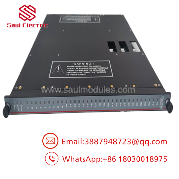
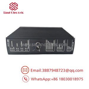
- 3501TN2
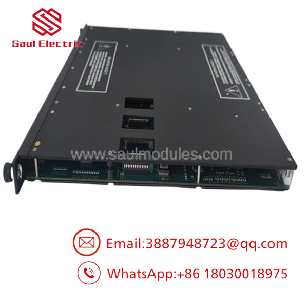
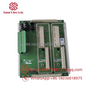
- 3501TN2
Transparency SOP: QA & Testing
- Step 1: Visual & Pin Integrity Audit
Every 3501TN2 undergoes microscopic pin-alignment testing, conformal coating verification, and backplane guide key checks to guarantee smooth mechanical insertion.
- Step 2: Live Chassis & TriBus Sync Test
The card is installed into an active Tricon chassis system running test firmware to confirm power rail stability, TriBus address decoding, and microprocessor handshake responses.
- Step 3: 32-Channel High-Voltage Injection
Using automated test equipment, we step voltage across all 32 channels from 0V up to 155V AC and DC. We verify precise switching thresholds (OFF to ON >86V, ON to OFF <28V) and turn-on timing specs.
- Step 4: Stuck-ON Diagnostic Check
Internal self-test routines are executed to verify that onboard microprocessors accurately detect simulated shorted or stuck-ON input optocouplers without passing false data to the Main Processors.
The Veteran’s Tech Trap Guide
⚠️ 115V AC vs. 24V DC Field Wiring Mixed Danger: Ensure your panel wiring reflects 115V AC/DC field supply before landing conductors on the External Termination Panel (ETP). Accidentally connecting 24V DC field loops to a 3501TN2 will cause channels to stay perpetually in the OFF state because 24V fails to cross the card’s >86V threshold. Conversely, landing 115V on a 24V card like a 3501E or 3503E will destroy field interface components.
PRO TIP: Managing High Heat Dissipation
A fully energized 3501TN2 running 32 channels ON at maximum field voltage (155V) can dissipate upwards of 90 Watts of thermal energy per slot. Always verify that chassis cooling fan trays are clean and operating at full CFM capacity. High ambient rack temperatures are the number-one driver of premature optocoupler degradation in 115V high-density cards.
⚠️ Field Contact Chatter & Debounce Times: The 3501TN2 features hardware filtering with an ON-to-OFF delay of up to 15 ms. If your application relies on extremely fast sequence-of-events (SOE) timestamping under 2 ms, route those points to high-speed digital input cards or specialized SOE modules rather than standard 115V AC input cards.
Dynamic FAQ
Q: Can the Triconex 3501TN2 handle both 115V AC and 115V DC inputs simultaneously?
A: Yes. The 3501TN2 is designed to accept either 115V AC (47–63 Hz) or 115V DC field inputs across its operational range of 90 to 155V. Because channels are individually isolated, you can mix AC and DC field supplies across different channels on the same card provided field wiring guidelines are met.
Q: What is the main operational difference between the 3501T and the 3501TN2?
A: The 3501TN2 is an enhanced hardware revision featuring updated board components and improved noise rejection on field lines while maintaining full functional backward compatibility with standard 3501T chassis slots and ETP interface cabling.
Q: Can I plug a 3501TN2 into an active system without taking the plant offline?
A: Yes. Triconex chassis support online hot-swapping. Inserting the module into a spare slot triggers automatic self-diagnostics and system synchronization before it assumes active input scanning.
Q: What kind of warranty comes with your surplus or reconditioned 3501TN2 cards?
A: All new surplus and reconditioned 3501TN2 modules are backed by a full 1-year functional replacement warranty and arrive with complete bench test records.
Q: What happens on the Main Processors if one channel fails its internal diagnostic check?
A: Because each channel is processed by three independent circuits, a failure on one leg is out-voted by the other two healthy legs. The module flags a channel fault LED and logs an alarm in TriStation 1131, but the system continues executing safe control without dropping the safety function.

 Start Chat


