





Description
Product Introduction & Engineering Value
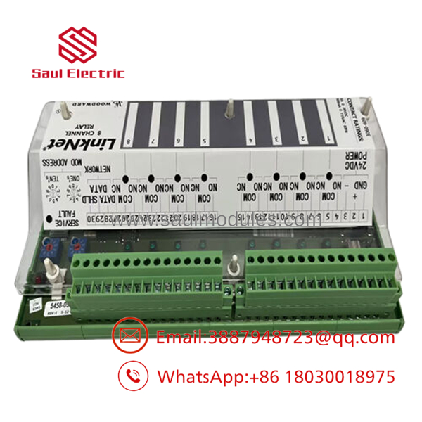
It is a massive headache when your central control chassis runs completely out of motherboard slots just as you need to interlock additional fuel skid isolation valves. The Woodward 9905-973 bypasses this physical chassis limitation completely, functioning as a distributed LinkNet relay node that can be dropped onto a serial data ring hundreds of feet away from the central CPU.
I prefer this architecture for complex steam and gas turbine helper installations because it relocates high-current relay switching closer to the actual field actuators. By converting raw data commands into physical contact closures right at the machine skid, the 9905-973 dramatically reduces inter-cabinet wiring bundles and curtails high-frequency switching noise inside the primary automation enclosure.
Technical Specifications
The LinkNet 8-channel relay module relies heavily on distinct network layouts and specific contact point capacities. These parameters are outlined below:
| Core Electrical & Network Parameter | Field Constraint / Configuration Value |
| Logic Supply Voltage Requirements | 18 to 32 VDC nominal operating range (24 VDC baseline) |
| Onboard Contact Configuration | 8 independent Form-C (SPDT – Single Pole Double Throw) relays |
| Resistive Contact Rating | 5.0 A at 28 VDC / 5.0 A at 120 VAC resistive loads |
| Inductive Contact Rating | 2.0 A at 28 VDC / 2.0 A at 120 VAC (highly inductive fields) |
| Network Interface Protocol | Proprietary Woodward LinkNet serial high-speed communication |
| Address Selection Method | Dual rotary decimal switches (00 to 99 range selection) |
| Isolation Barrier Rating | 500 VDC between internal network logic and field terminal circuits |
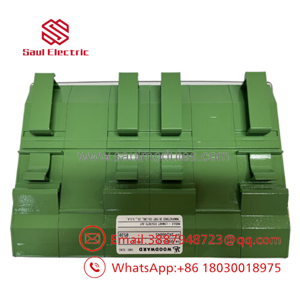
| Mounting Footprint Profile | Vertical or horizontal 35mm industrial DIN rail snap-lock |
Field Application & The “Trench” Experience
We were troubleshooting a triple-modular redundant (TMR) MicroNet system on a mechanical-drive gas turbine platform where an older interlock card had failed due to repetitive thermal tracking. The field team could not afford the weeks of downtime required to re-engineer the backplane logic. We mounted a 9905-973 right inside the local actuator enclosure, linked it back to the MicroNet CPU via a shielded twin-axial LinkNet network, and assigned its hardware node address to match the existing sequential valve mapping. The engine was fired back up within six hours, maintaining full structural isolation between the main control room and the messy, oil-slicked actuator floor.
- Gas Turbine Fuel Valve Sequencing: Directly pulsing primary fuel manifold stop and vent solenoid packages.
- Distributed Lube Oil Pump Interlocking: Controlling the secondary DC backup lubrication starter circuits based on pressure drop alerts.
- Remote Generator Breaker Trip Relaying: Driving auxiliary remote trip coils inside medium-voltage switchgear vaults without long wire runs.
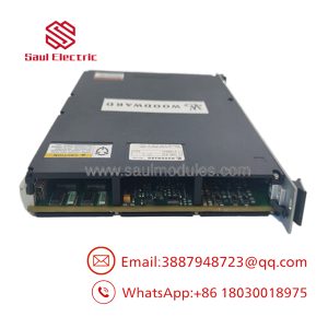
- 9905-973
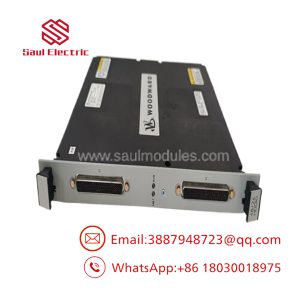
- 9905-973
Transparency SOP: QA & Testing
Every single 9905-973 unit undergoes an exhaustive diagnostic verification pipeline inside our engineering workshop:
- Terminal Integrity Evaluation: We mechanically torque and visually inspect the screw terminal barriers to ensure zero pin stress or soldering fracturing.
- Dynamic Cycle Testing: Every one of the 8 Form-C contact sets is cycled 500 times under full electrical load while measuring contact resistance to guarantee absolute zero-bounce switching.
- LinkNet Buffer Validation: We connect the module to a live test-bench MicroNet master rack, shifting network baud rates to ensure the rotary dials translate the module address correctly without data frame drops.
- Galvanic Leakage Checking: High-potential breakdown checking ensures the isolation barriers completely prevent field voltage leakage from bleeding back into the data network lines.
The Veteran’s Tech Trap Guide
⚠️ THE DISADVANTAGE OF THE DRY-CONTACT: Do not route mixed voltages across the same 9905-973 module housing if you can avoid it. While each channel’s Form-C contacts are independent, running 120 VAC on Channel 1 directly adjacent to a sensitive 24 VDC safety loop on Channel 2 invites accidental tracking shorts across the terminal divider if field wiring is pulled too tight or gets wet.
PRO TIP: LinkNet networks require a fixed termination resistor at the absolute physical end of the communication string. If you drop a replacement 9905-973 into the middle of an active string, make sure you do not accidentally move or leave out the termination jumper that was placed on the old unit. Missing this termination introduces signal reflections that will cause random communication timeouts across all other LinkNet blocks on that loop.
Dynamic FAQ
- Q: Do I need special programming tools to update the internal firmware when replacing this module?
- A: No. The 9905-973 is a purely hardware-configured, distributed device. It pulls its functional operating parameters and logic execution profiles directly from the master controller application code based entirely on its rotary address dial settings.
- Q: Can this unit handle AC and DC voltages simultaneously across different relay channels?
- A: Yes, the contacts are separate from each other. However, you must observe proper safety separation distances and wire sizing practices inside your electrical marshalling box to keep things clean.
- Q: What does a flashing “Service/Fault” LED under the clear front faceplate mean?
- A: If it flashes slowly, it means the module has lost its LinkNet communication link with the central CPU. If it stays solid red, the module has failed its internal self-test and needs a hardware replacement.
- Q: What warranty coverage do you provide on these older LinkNet parts?
- A: We fully back every single New Surplus or re-certified Refurbished 9905-973 module with our ironclad 1-year operational replacement warranty, shipping complete with our signed shop test certificates.

 Start Chat


