





Description
Product Introduction & Engineering Value
The 9907-018 belongs to the older Woodward 2301A control architecture, where one electronic controller closes the speed-control loop between a speed-sensing device and a proportional actuator. In generator applications, it can also participate in load sharing between parallel prime movers.
For maintenance teams, the critical identification points are 2301A, low-voltage supply, forward-acting configuration, and the correct actuator/output arrangement. A replacement should be matched against the existing control’s nameplate and application configuration rather than selected solely by the “2301A” family name. Woodward provides a product-history lookup based on the actual part and serial number.
Technical Specifications
| Specification | 9907-018 |
|---|---|
| Manufacturer | Woodward |
| Part Number | 9907-018 |
| Control Family | 2301A |
| Series | 9907 |
| Control Function | Speed and load sharing |
| Acting Direction | Forward acting |
| Power Supply Class | Low voltage |
| Operating Supply Range | 18–40 VDC for the low-voltage 2301A architecture |
| Nominal Supply | 24 VDC |
| Actuator Current | 0–200 mA class |
| Speed Ranges | 500–1,500; 1,000–3,000; 2,000–6,000; 4,000–12,000 Hz |
| Control Modes | Isochronous / droop |
| Mounting Environment | Control cabinet; not intended for direct engine mounting |
| Operating Temperature | –40 to +85°C |
| Typical Applications | Diesel/gas engines and steam/gas turbines |
The Woodward manual gives four selectable speed ranges and states that the factory setting is 2,000–6,000 Hz. Selecting the speed range requires calculating the maximum speed-sensor frequency from gear teeth and RPM.
Important note on 9907-018-specific data
Some secondary-market listings report different dimensions, temperature ratings, or electrical details for this part. For engineering work, the Woodward 2301A manual and the actual control identification label should take precedence over generic reseller specifications. Woodward itself recommends checking the product label and serial number through its product-history system.
How the 9907-018 Fits Into a Control System
A typical 2301A installation contains:
Speed sensor → 9907-018 controller → proportional actuator → fuel/steam metering device
For generator applications, the controller also receives generator/load information through current and potential transformers. Woodward describes the system as including the electronic control, speed-sensing device, proportional actuator, and CT/PT measurement circuits.
Isochronous operation
Isochronous control maintains constant prime-mover speed. Woodward describes its use for:
- Single prime-mover operation
- Multiple prime movers operating on an isolated bus with load-sharing controls
- Base loading against an infinite bus with an appropriate load-control accessory
Droop operation
Droop control establishes a speed/load relationship and can be used for:
- A single prime mover operating against an infinite bus
- Parallel operation of multiple prime movers
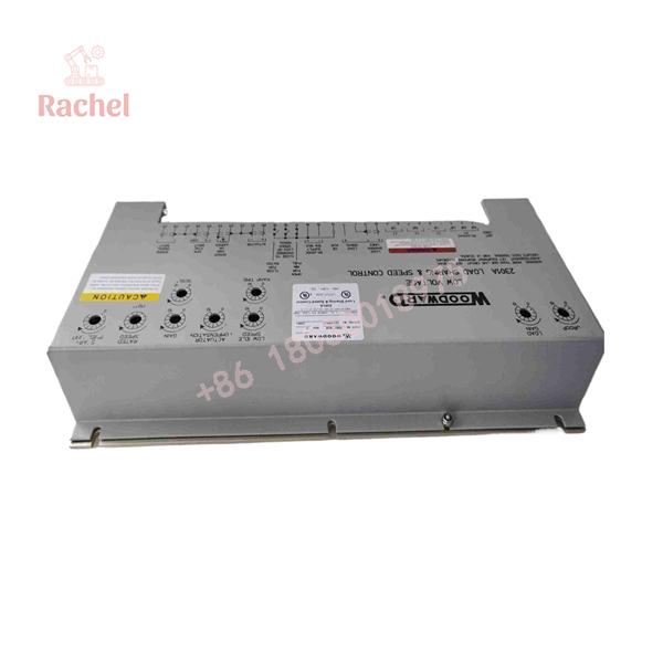
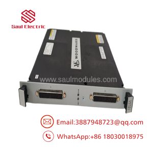
9907-018
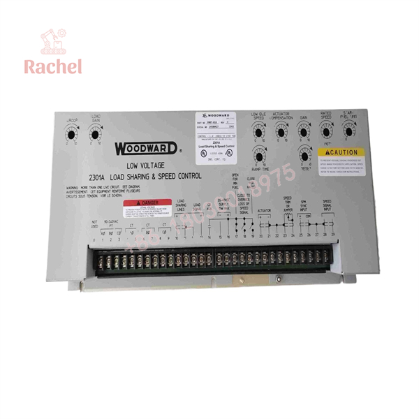
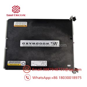
9907-018
Field Application & Trench Experience
Example: Parallel diesel-generator system
A plant operates two diesel generators in parallel. One generator begins carrying an abnormal share of the active load while its measured engine speed remains within the expected operating range.
An experienced technician would not immediately replace the actuator.
The troubleshooting path would include:
- Confirm the 9907-018 supply voltage.
- Verify the selected speed range against the actual speed-sensor frequency.
- Check CT polarity and phase relationships.
- Verify the load-sharing lines.
- Confirm the isochronous/droop configuration.
- Check actuator current and mechanical response.
- Compare the behavior against the other generator’s governor system.
Woodward specifically provides procedures for CT phasing, load gain, droop adjustment, speed-sensor checks, and load-sharing operation in the 2301A manual.
Other application scenarios
Diesel generator sets
- Engine speed regulation
- Parallel-generator load sharing
- Base-load operation
Gas engine generator systems
- Governor control
- Generator loading
- Parallel-unit coordination
Steam turbine systems
- Prime-mover speed control
- Load regulation
- Mechanical actuator control
Gas turbine systems
- Speed/load control interfaces
- Fuel-control actuator applications
These are application categories documented for the 2301A family; exact suitability depends on the installed actuator, sensor, generator instrumentation, and control configuration.
QA & Testing SOP for New Surplus or Refurbished Stock
For a legacy 9907-018, a functional test is much more useful than a visual inspection alone.
Incoming inspection
Identity
- Verify WOODWARD marking.
- Confirm 9907-018 on the nameplate.
- Record serial number and revision information.
- Compare the replacement with the removed unit.
Physical condition
- Inspect the sheet-metal chassis.
- Check terminals and connectors.
- Look for corrosion, impact damage, contamination, or heat discoloration.
- Inspect adjustment potentiometers and switches.
Electrical verification
A qualified test bench should verify:
- Low-voltage power input
- Speed-sensor input
- Correct speed-range selection
- Actuator output
- External speed-trim circuit
- Isochronous/droop functionality
- Load-sharing interface
- CT/PT measurement circuits where applicable
The Woodward manual specifies a –40 to +85°C operating environment, requires adequate ventilation, and says the control should not be mounted directly on the engine.
Surplus-stock documentation
For New Surplus inventory, the supplier should ideally provide:
- Actual product photographs
- Nameplate photograph
- Serial/part number
- Condition statement
- Power-up test results
- Functional test report
- Warranty period
“New Surplus” should not automatically be interpreted as current factory production.
Veteran’s Tech Trap Guide
⚠️ Trap 1 — Selecting by “2301A” alone
The 9907 family contains multiple configurations with differences in:
- Supply voltage
- Forward/reverse action
- Actuator arrangement
- Speed range
- Deceleration-ramp options
The Woodward 2301A documentation makes these configuration differences explicit.
PRO TIP: Match the complete part number, not simply “2301A.”
⚠️ Trap 2 — Getting the speed range wrong
The controller supports four speed-frequency ranges. Woodward warns that selecting an inappropriate range can create an overspeed hazard.
The speed-sensor frequency is calculated as:
Sensor Frequency = Number of Gear Teeth × RPM ÷ 60
Use the maximum intended prime-mover speed when selecting the range.
⚠️ Trap 3 — Treating a speed-control fault as an actuator fault
A bad actuator is only one possibility.
The 2301A control depends on the complete loop:
Speed pickup → controller → actuator → fuel/steam system
A failed speed signal, incorrect S1 speed-range setting, CT phasing problem, load-sharing signal issue, or incorrect adjustment can produce symptoms that look like an actuator problem.
⚠️ Trap 4 — Ignoring shield termination
Woodward calls for shielded twisted-pair signal wiring and specifies that exposed conductor beyond the shield should be kept short. It also warns against routing shielded signal wires with high-current conductors.
For older generator installations, wiring condition can be just as important as the controller itself.
Dynamic FAQ
What is Woodward 9907-018?
It is a 2301A-series electronic load-sharing and speed-control unit in the low-voltage configuration. It is used to control the speed/load of prime movers including diesel and gas engines and steam or gas turbines.
Is 9907-018 a PLC or I/O module?
No. It is a dedicated electronic governor/speed and load-sharing control, not a general-purpose PLC or distributed I/O card.
What voltage does 9907-018 use?
The 9907 low-voltage 2301A architecture operates from 18–40 VDC, with 24 VDC as the nominal system voltage.
What actuator output does it provide?
The 2301A 9907 family uses a 0–200 mA actuator-current range for the applicable configurations. The exact actuator and acting arrangement must be confirmed from the control identification and application documentation.
Can 9907-018 be replaced by another 9907-series controller?
Not automatically. Different 9907 models can have different voltage classes, forward/reverse action, actuator arrangements, and optional functions. A replacement should be matched by exact part number and application configuration.
Is New Surplus 9907-018 authentic?
“New Surplus” describes the condition, not automatically the manufacturing source. For procurement, request the actual Woodward nameplate, serial number, packaging information when available, and a functional test report. Woodward’s product-history system can be used to check product information using the part and serial number.
What warranty should I expect?
Warranty depends on the supplier and stock condition. A quotation should explicitly state whether the unit is New Surplus, unused original packaging, repaired, or refurbished, together with the applicable warranty period.

 Start Chat


